Galileo Experiment Guide
This Tutorial is Retired!
This tutorial covers concepts or technologies that are no longer current. It's still here for you to read and enjoy, but may not be as useful as our newest tutorials.
 HelloTechie
 SIK Galileo - Part 10: Reading a Soft Potentiometer
Introduction
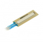
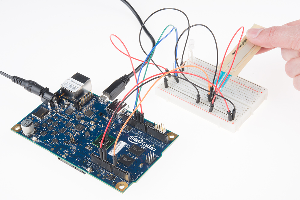
In this circuit, we are going to use yet another kind of variable resistor – this time, a soft potentiometer (or soft pot). This is a thin and flexible strip that can detect where pressure is being applied. By pressing down on various parts of the strip, you can vary the resistance from 100 to 10k ohms. You can use this ability to track movement on the soft pot, or simply as a button. In this circuit, we’ll get the soft pot up and running to control an RGB LED.
Parts Needed
You will need the following parts:
- 1x Breadboard
- 1x Galileo
- 1x Soft Potentiometer
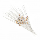
- 1x 10k resistor
- 3x 330Ω resistors
- 1x RGB LED
- 9x Jumper Wires
If you are following through all of the SIK Galileo tutorials we suggest getting using parts:


View the SparkFun Inventor's Kit for Galileo wishlist, to see the parts needed to go through the all the experiments.
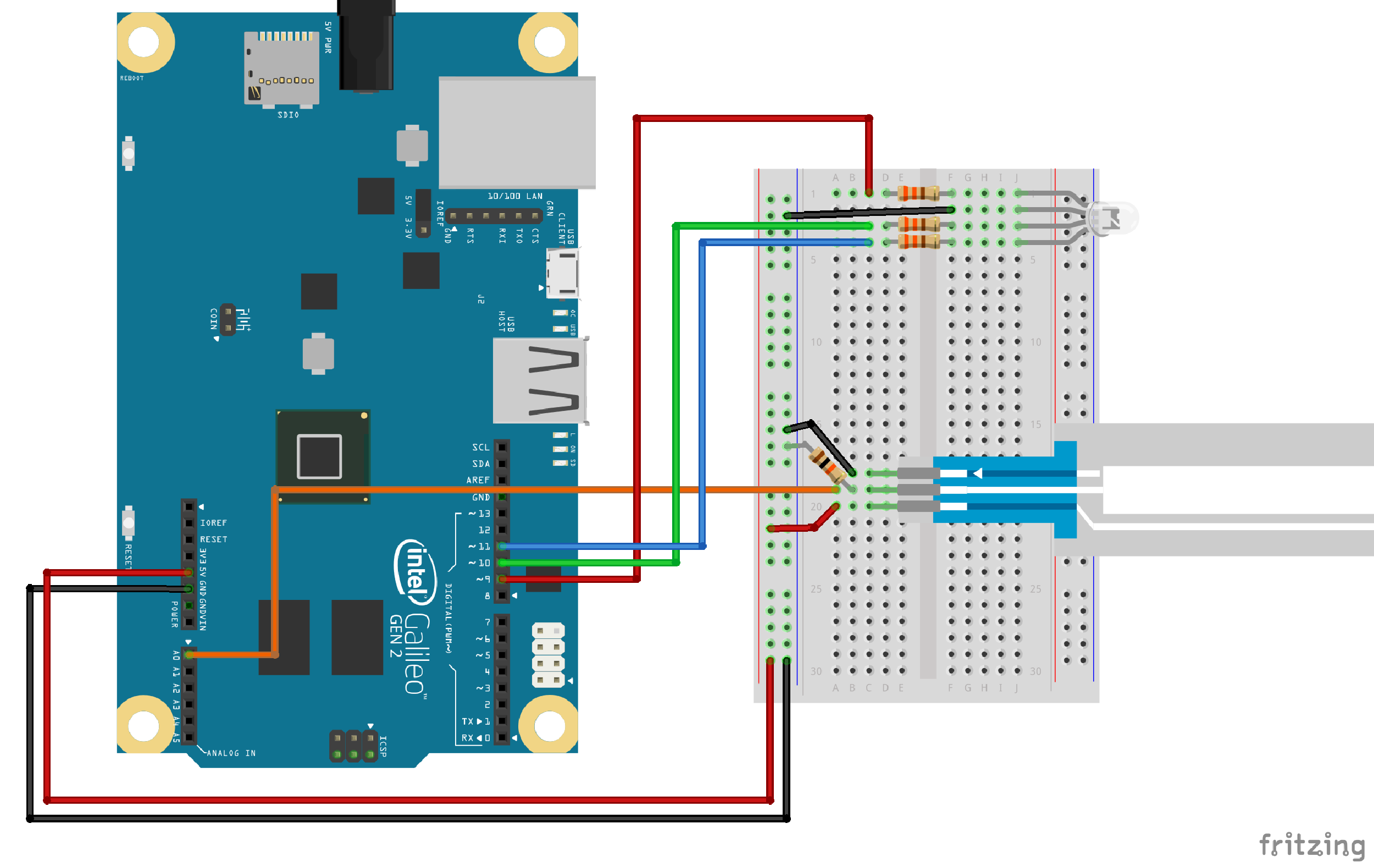
Hardware Hookup
Ready to start hooking everything up? Check out the Fritzing diagram below, to see how everything is connected. Pay special attention to the component’s markings indicating how to place it on the breadboard. Polarized components can only be connected to a circuit in one direction.
Fritzing Diagram
Code To Note
language:cpp
redValue = constrain(map(RGBposition, 0, 341, 255, 0), 0, 255)
 + constrain(map(RGBposition, 682, 1023, 0, 255), 0, 255);


greenValue = constrain(map(RGBposition, 0, 341, 0, 255), 0, 255)
 - constrain(map(RGBposition, 341, 682, 0,255), 0, 255);


blueValue = constrain(map(RGBposition, 341, 682, 0, 255), 0, 255)
- constrain(map(RGBposition, 682, 1023, 0, 255), 0, 255);
These big, scary functions take a single Value (RGBposition) and calculate the three RGB values necessary to create a rainbow of color. The functions create three "peaks" for the red, green, and blue values, which overlap to mix and create new colors. See the code for more information! Even if you're not 100% clear how it works, you can copy and paste this (or any) function into your own code and use it yourself.
**Copy and paste the following code into the Arduino IDE. Hit upload and see what happens! **
language:cpp
/*
SparkFun Inventor's Kit Galileo
Example sketch 10
SOFT POTENTIOMETER
Use the soft potentiometer to change the color
of the RGB LED
The soft potentiometer is a neat input device that detects
pressure along its length. When you press it down with a finger
(it works best on a flat surface), it will change resistance
depending on where you're pressing it. You might use it to make
a piano or light dimmer; here we're going to use it to control
the color of an RGB LED.
Hardware connections:
Soft potentiometer:
The soft potentiometer is the large plastic strip with three
pins. We'll be connecting it as a voltage divider, just like
we did with the knob-type potentiometer back in circuit #2.
Connect the middle pin to ANALOG IN pin 0 on the Arduino.
Connect one side to 5V.
Connect the other side to GND.
Also connect a 10K resistor from the middle pin to GND.
TIP: the soft pot will only work while you're actively
pressing on it; at other times it will "float" to random
values. To prevent this, we've added a 10K pull-down resistor
to the middle pin (output voltage). This will keep the output
at zero volts when the pot is not being pressed.
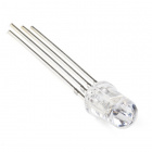
RGB LED:
An RGB LED is actually three LEDs (red, green, and blue)
in one package. When we run them at different brightnesses,
they mix to form new colors.
Starting at the flattened edge of the flange on the LED,
the pins are ordered RED, COMMON, GREEN, BLUE.
Connect RED to a 330 Ohm resistor.
Connect the other end of the resistor to Arduino digital pin 9.
Connect COMMON to GND.
Connect GREEN through a 330 Ohm resistor.
Connect the other end of the resistor to Arduino digital pin 10.
Connect BLUE through a 330 Ohm resistor.
Connect the other end of the resistor to Arduino digital pin 11.
This sketch was written by SparkFun Electronics,
with lots of help from the Arduino community.
This code is completely free for any use.
Visit http://learn.sparkfun.com/products/2 for SIK information.
Visit http://www.arduino.cc to learn about the Arduino.
Version 2.0 6/2012 MDG
*/
// Constants for LED connections (note that these must be
// PWM pins, which are marked with "PWM" or have a "~" symbol
// next to them on the board).
const int RED_LED_PIN = 9; // Red LED Pin
const int GREEN_LED_PIN = 10; // Green LED Pin
const int BLUE_LED_PIN = 11; // Blue LED Pin
const int SENSOR_PIN = 0; // Analog input pin
// Global PWM brightness values for the RGB LED.
// These are global so both loop() and setRGB() can see them.
int redValue, greenValue, blueValue;
void setup()
{
// No need for any code here
// analogWrite() sets up the pins as outputs
}
void loop()
{
int sensorValue;
// Read the voltage from the softpot (0-1023)
sensorValue = analogRead(0);
// We've written a new function called setRGB() (further down
// in the sketch) that decodes sensorValue into a position
// on the RGB "rainbow", and sets the RGB LED to that color.
setRGB(sensorValue);
}
// setRGB()
// Set a RGB LED to a position on the "rainbow" of all colors.
// RGBposition should be in the range of 0 to 1023 (such as
// from an analog input).
void setRGB(int RGBposition)
{
int mapRGB1, mapRGB2, constrained1, constrained2;
// Here we take RGBposition and turn it into three RGB values.
// The three values are computed so that the colors mix and
// produce a rainbow of colors across the 0-1023 input range.
// For each channel (red green blue), we're creating a "peak"
// a third of the way along the 0-1023 range. By overlapping
// these peaks with each other, the colors are mixed together.
// This is most easily shown with a diagram:
// http://sfecdn.s3.amazonaws.com/education/SIK/SchematicImages/Misc/RGB_function.jpg
// Create the red peak, which is centered at 0.
// (Because it's centered at 0, half is after 0, and half
// is before 1023):
mapRGB1 = map(RGBposition, 0, 341, 255, 0);
constrained1 = constrain(mapRGB1, 0, 255);
mapRGB2 = map(RGBposition, 682, 1023, 0, 255);
constrained2 = constrain(mapRGB2, 0, 255);
redValue = constrained1 + constrained2;
// Create the green peak, which is centered at 341
// (one-third of the way to 1023):
// Note that we've nested the functions by putting the map()
// function inside the constrain() function. This can make your
// code more compact, and requires fewer variabls:
greenValue = constrain(map(RGBposition, 0, 341, 0, 255), 0, 255)
- constrain(map(RGBposition, 341, 682, 0,255), 0, 255);
// Create the blue peak, which is centered at 682
// (two-thirds of the way to 1023):
blueValue = constrain(map(RGBposition, 341, 682, 0, 255), 0, 255)
- constrain(map(RGBposition, 682, 1023, 0, 255), 0, 255);
// Now we have all three brightnesses,
// we just need to display the computed color:
analogWrite(RED_LED_PIN, redValue);
analogWrite(GREEN_LED_PIN, greenValue);
analogWrite(BLUE_LED_PIN, blueValue);
// Feel free to use this function in your own code!
}
What You Should See
You should see the RGB LED change colors in accordance with how you interact with the soft potentiometer. If it isn't working, make sure you have assembled the circuit correctly and verified and uploaded the code to your board, or see the troubleshooting section.
Real World Application
The knobs found on many objects, like a radio for instance, are using similar concepts to the one you just completed for this circuit.
Troubleshooting
LED Remains Dark or Shows Incorrect Color
With the four pins of the LED so close together, it’s sometimes easy to misplace one. Try double checking each pin is where it should be.
Bizarre Results
The most likely cause of this is if you’re pressing the potentiometer in more than one position. This is normal and can actually be used to create some neat results.