Galileo Experiment Guide
This Tutorial is Retired!
This tutorial covers concepts or technologies that are no longer current. It's still here for you to read and enjoy, but may not be as useful as our newest tutorials.
 HelloTechie
 SIK Galileo - Part 13: Using Relays
Introduction
In this circuit, we are going to use some of the lessons we learned in Circuit 12 to control a relay. A relay is basically an electrically controlled mechanical switch. Inside that harmless looking plastic box is an electromagnet that, when it gets a jolt of energy, causes a switch to trip. In this circuit, you’ll learn how to control a relay like a pro – giving your Galileo even more powerful abilities!
Parts Needed
You will need the following parts:
- 1x Breadboard
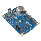
- 1x Galileo
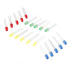
- 2x LEDs
- 2x 330Ω Resistors
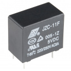
- 1x Relay (SPDT)
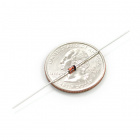
- 1x Diode 1N4148
- 1x NPN Transistor
- 14x Jumper Wires
If you are following through all of the SIK Galileo tutorials we suggest using these parts:


View the SparkFun Inventor's Kit for Galileo wishlist, to see the parts needed to go through the all the experiments.
Suggested Reading
Before continuing on with this experiment, we recommend you be familiar with the concepts in the following tutorial:
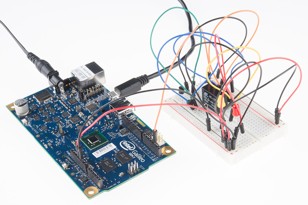
Hardware Hookup
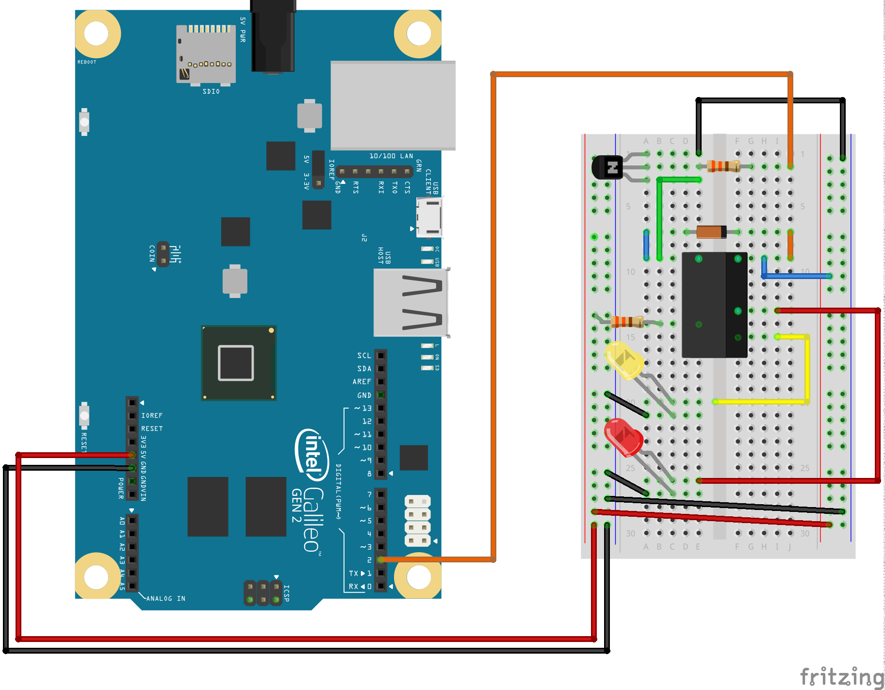
Ready to start hooking everything up? Check out the Fritzing diagram below, to see how everything is connected. Pay special attention to the component’s markings indicating how to place it on the breadboard. Polarized components can only be connected to a circuit in one direction.
Fritzing Diagram
Code To Note
digitalWrite(relayPin, HIGH);
When we turn on the transistor, which in turn energizes the relay's coil, the relay's switch contacts are closed. This connects the relay's COM pin to the NO (Normally Open) pin. Whatever you've connected using these pins will turn on. (Here we're using LEDs, but this could be almost anything.)
digitalWrite(relayPin, LOW);
The relay has an additional contact called NC (Normally Closed). The NC pin is connected to the COM pin when the relay is OFF. You can use either pin depending on whether something should be normally on or normally off. You can also use both pins to alternate power to two devices, much like railroad crossing warning lights.
**Copy and paste the following code into the Arduino IDE. Hit upload and see what happens! **
language:cpp
/*
SparkFun Inventor's Kit Galileo
Example sketch 13
RELAYS
Use a transistor to drive a relay
A relay is a electrically-controlled mechanical switch.
It can control much more voltage and current than an Arduino pin
(or the transistor included in your kit) can. If you want to use
the Arduino to control a 120V bulb, coffee maker, or other high-
power device, a relay is an excellent way to do that. Because
the relay needs more power to switch than an Arduino pin can
provide, we'll use a transistor to drive the relay in exactly
the same way we used a transistor to drive a motor in circuit 12.
A relay consists of a coil of wire, and switch contacts. When
you apply power to the coil, it becomes magnetized, and pulls
the switch contacts closed. Since the switch contacts are
completely isolated from the Arduino, you can safely use a
relay to control normally dangerous voltages (but please only do
this if you already know how to safely work with high voltage!).
The relay has three contact pins, COM (common), NC (Normally
Closed), and NO (Normally Open). When the relay is turned off,
the COM pin is connected to the NC (Normally Closed) pin. When
the relay is turned on, the COM pin is connected to the NO
(Normally Open) pin.
This code is very simple - it turns the relay on for one second,
and off for one second, the same as the blink sketch!
Hardware connections:
Transistor:
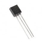
The transistor has three pins. Looking at the flat side with
the pins down, the order is COLLECTOR, BASE, EMITTER.
Connect the BASE pin through a 1K resistor to digital pin 2.
Connect the EMITTER pin to GND.
Relay coil:
The relay has pins for a coil (which you use to control the
relay), and contacts (which you connect to the device you'd
like to switch). The top or bottom of the relay should have
a symbol indicating the coil pins.
Connect one side of the coil to the COLLECTOR pin
on the transistor.
Connect other side of the coil to 5V.
Diode:
The relay has a coil that you energize to close the switch.
When you disconnect power from a coil, the coil will generate
a voltage spike that can damage the transistor. This diode
protects the transistor from the voltage spike.
Connect the side of the diode with the band (cathode) to 5V
Connect the other side of the diode (anode) to the COLLECTOR
pin of the transistor.
Relay contacts and LEDs:
We'll use the relay contacts to turn LEDs on and off, but you
can use them to switch almost anything on and off.
Connect the COMMON side of the switch to a 330 Ohm resistor.
Connect the other side of the above resistor to 5V.
Connect the NC (Normally Closed) side of the switch to the
positive (longer) leg of LED 1.
Connect the NO (Normally Open) side of the switch to the
positive (longer) leg of LED 2.
Connect the negative sides (shorter leg) of both LEDs to GND.
This sketch was written by SparkFun Electronics,
with lots of help from the Arduino community.
This code is completely free for any use.
Visit http://learn.sparkfun.com/products/2 for SIK information.
Visit http://www.arduino.cc to learn about the Arduino.
Version 2.0 6/2012 MDG
*/
const int relayPin = 2; // use this pin to drive the transistor
const int timeDelay = 1000; // delay in ms for on and off phases
// You can make timeDelay shorter, but note that relays, being
// mechanical devices, will wear out quickly if you try to drive
// them too fast.
void setup()
{
pinMode(relayPin, OUTPUT); // set pin as an output
}
void loop()
{
digitalWrite(relayPin, HIGH); // turn the relay on
delay(timeDelay); // wait for one second
digitalWrite(relayPin, LOW); // turn the relay off
delay(timeDelay); // wait for one second
}
What You Should See
You should be able to hear the relay contacts click, and see the two LEDs alternate illuminating at 1-second intervals. If you don't, double-check that you have assembled the circuit correctly, and uploaded the correct sketch to the board. Also, see the troubleshooting section.
Real World Application
Garage door openers use relays to operate. You might be able to hear the clicking if you listen closely.
Troubleshooting
LEDs Not Lighting
Double-check that you've plugged them in correctly. The longer lead (and non-flat edge of the plastic flange) is the positive lead.
No Clicking Sound
The transistor or coil portion of the circuit isn't quite working. Check the transistor is plugged in the right way.
Not Quite Working
The included relays are designed to be soldered rather than used in a breadboard. As such you may need to press it in to ensure it works (and it may pop out occasionally).
When you’re building the circuit be careful not to mix up the temperature sensor and the transistor, they’re almost identical.