Garmin LIDAR-Lite v4 (Qwiic) Hookup Guide
Hardware Overview
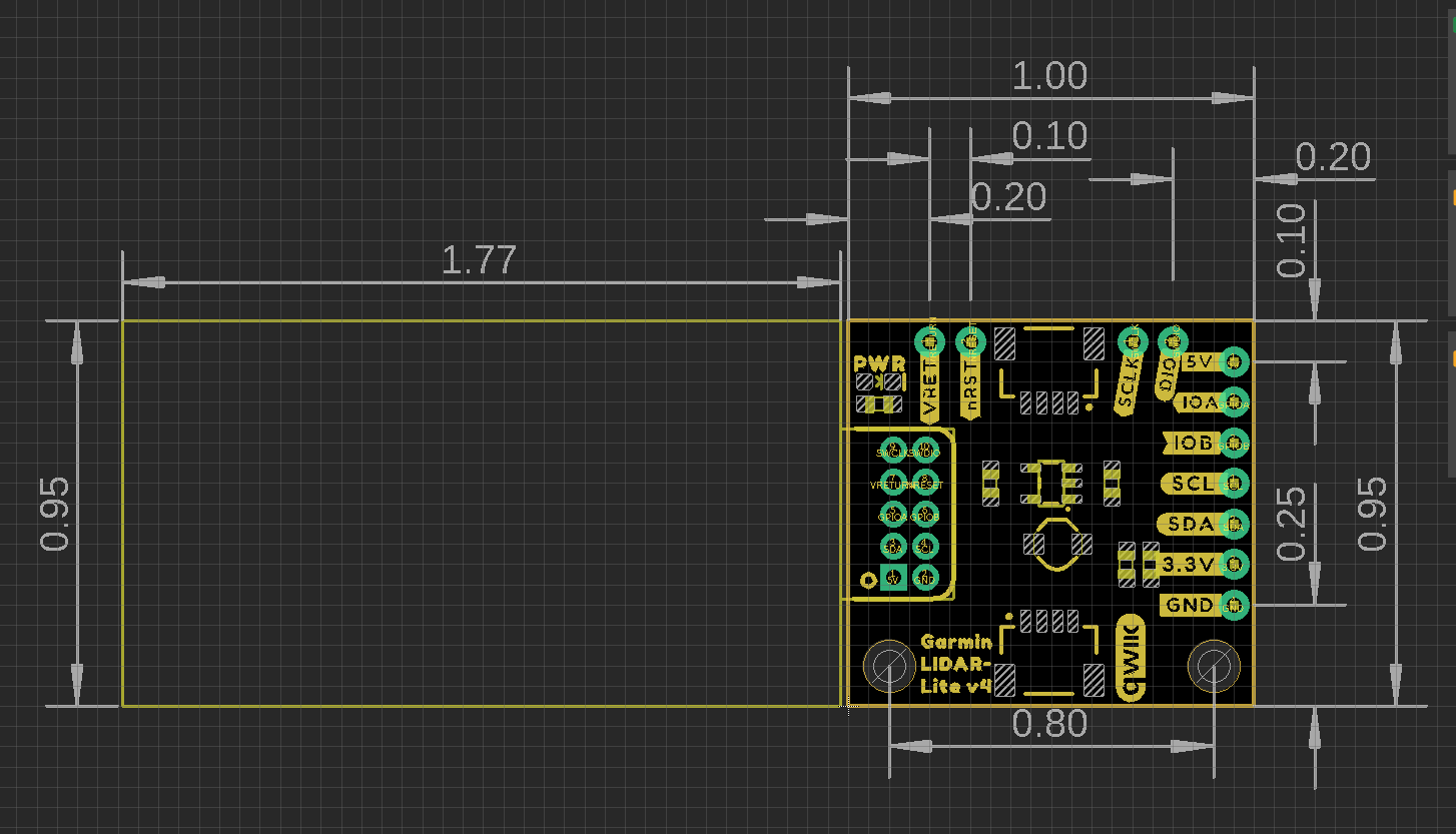
Board Dimensions
The Garmin LIDAR-Lite v4 (Qwiic) has an attached 1" x 1" Qwiic board for ease of use. The overall product dimensions are approximately 2.8" x 1.0" x 0.9" (L x W x H), with more detailed measurements in the drawing below.
Mounting Options
The Garmin LIDAR-Lite v4 operation manual lists zipties and double-sided tape as attachment methods. There are notches on the sensor housing that appear to be meant for a ziptie.
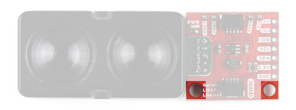
With our Qwiic version, we provide two screw holes on the Qwiic board as an additional mounting option. The holes are compatible with 4-40 screws and hardware.
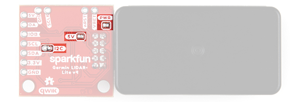
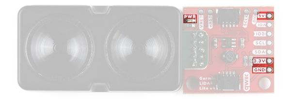
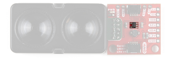
Power
There is a power status LED to indicate when the Garmin LIDAR-Lite v4 (Qwiic) sensor is powered. Power the board either through the polarized Qwiic connector system or the breakout pins (3.3V or 5V and GND) provided. The Qwiic system is meant to run on 3.3V, be sure that you are NOT using another voltage when using the Qwiic system. A jumper is available on the back of the board to remove power to the LED for low-power applications (see Jumpers section below).
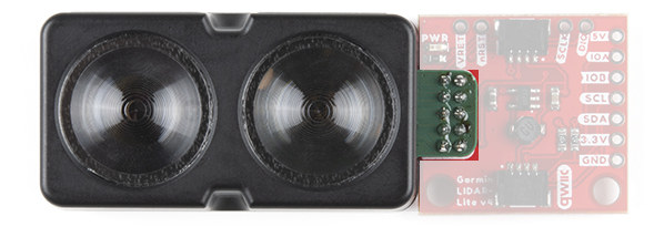
DC-DC Converter
The Garmin LIDAR-Lite v4 sensor requires 5V to operate. In order to provide 5V to the sensor from the 3.3V line of the Qwiic connector, a DC-to-DC voltage converter is utilized. This can also be referred to as the buck/boost converter/circuit. For more details, check out the XC9140 datasheet.
Garmin LIDAR-Lite v4
The Garmin® LIDAR-Lite v4 is a distance measurement sensor. For more details on the sensor, please refer to the operation manual and technical specifications.
Sensor Characteristics
The power and current consumption characteristics listed below are from the operation manual and technical specifications. However, these specifications are for the sensor itself.
To prevent brown outs, users should be wary when attaching several Qwiic LIDAR-Lite v4s to the Qwiic connect system. Users can easily surpass the current (supply) limitation of their Qwiic microcontroller board. The Qwiic LIDAR-Lite v4 operates at 3.3V and we have measured the current consumption from the 3.3V line to be approximately:
- 120mA (idle)
- 165mA (during an acquisition)
Below, are the LIDAR sensor's electrical and performance characteristics, as listed in the operation manual and technical specifications datasheet.
| Characteristic | Description |
|---|---|
| Power (operating voltage) | 4.75 to 5.25 Vdc | Current Consumption |
2 mA idle
85 mA during an acquisition |
I/O Voltage | 3.3 V | Max Range | 5 cm to 10 m (1.97 in. to 32.8 ft.) | Resolution | 1 cm (0.4 in.) | Beam divergence | 4.77 degrees | LED Wavelength | 940 nm | Optical Aperture | 14.9 mm | Measurement Repeatability* |
± 1 cm up to 2 m ± 2 cm up to 4 m ± 5 cm up to 10m |
| I2C Address |
0x62 (Default)
Software configurable |
*NOTE: As measured indoors to a 90% reflective target; 1 cm is equivalent to 1 standard deviation. Measurements were obtained using high accuracy mode.
Qwiic and I2C
I2C Address
The Garmin LIDAR-Lite v4 (Qwiic)’s I2C address, 0x62 (7-bit), is factory set. However, this address is software configurable.
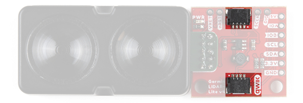
Qwiic Connectors
The simplest way to use the Garmin LIDAR-Lite v4 (Qwiic) is through the Qwiic connect system. The connectors are polarized for the I2C connection and power. (*They are tied to the corresponding power and I2C breakout pins.)
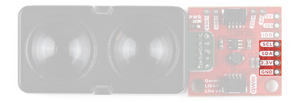
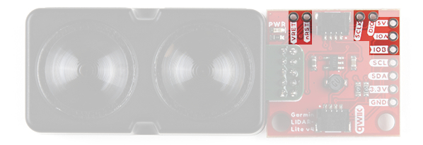
Breakout Pins
5V pin, the rest are 3.3V pins.The board also provides eleven labeled breakout pins. Besides the 5V (and GND) pin, the rest of the pins are only 3.3V tolerant.
I2C
You can connect these lines to the I2C bus of your microcontroller and power pins (3.3V and GND), if it doesn't have a Qwiic connector. The interrupt pins are also broken out to use for triggered events.
J-Link Debug and I/O Pins
Reprogramming the nRF52840 System on Chip (SoC) removes all pre-programmed factory software. SparkFun is NOT able to help you recover the software once it has been removed.
Before attempting to mess with the the nRF52840 System on Chip (SoC), we highly recommend users refer to the operation manual and technical specifications for other considerations and notices from the manufacturer.
The J-Link and I/O pins are also broken out for users, in case they wish to interface with the RF52840 SoC.
Jumpers
There are three jumpers on the board. Not sure how to cut or modify a jumper? Read here!
- Power LED - Cutting the
LEDjumper will remove the 1kΩ resistors andPWRLED from the 3.3V power. This is useful for lowering power consumption. - I2C Pull-Up - Cutting the
I2Cjumper will remove the 4.7kΩ pull-up resistors from the I2C bus. If you have many devices on your I2C bus you may want to remove these jumpers. - 5V Disconnect - Cutting the
5Vjumper on the board will disconnect the buck converter from the 5V power trace. This is useful when users power the board through the 5V breakout pin.