Getting Started with MicroMod
 Nate
Nate Hardware Hookup
Below are the steps to connect your MicroMod boards together!
Connecting a Processor to a Carrier Board
To get started with MicroMod, you'll need a processor board as well as a carrier board. Here we are using the Artemis MicroMod Processor Board with the Machine Learning Carrier Board. Align the top key of the MicroMod Artemis Processor Board to the screw terminal of the Machine Learning Carrier Board and angle the board into the socket. Insert the board at an angle into the M.2 connector.
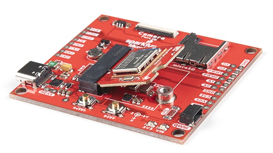
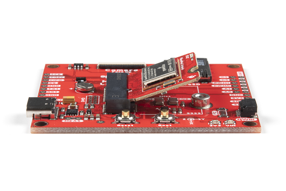
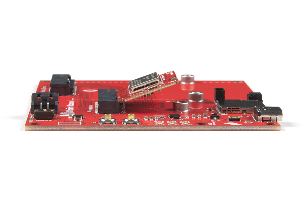
The Processor Board will stick up at an angle (at around 25°), as seen here:
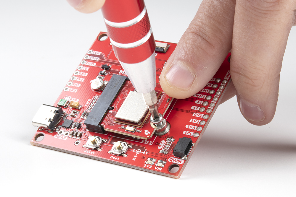
Once the board in the socket, gently hold the MicroMod Processor Board down and tighten the screw with a Phillip's head. We recommend the classic SparkFun reversible mini-screw driver, MicroMod Screwdriver, or the fancier pocket screw driver set but any #00, #0, or #1 Phillip's head driver will work.
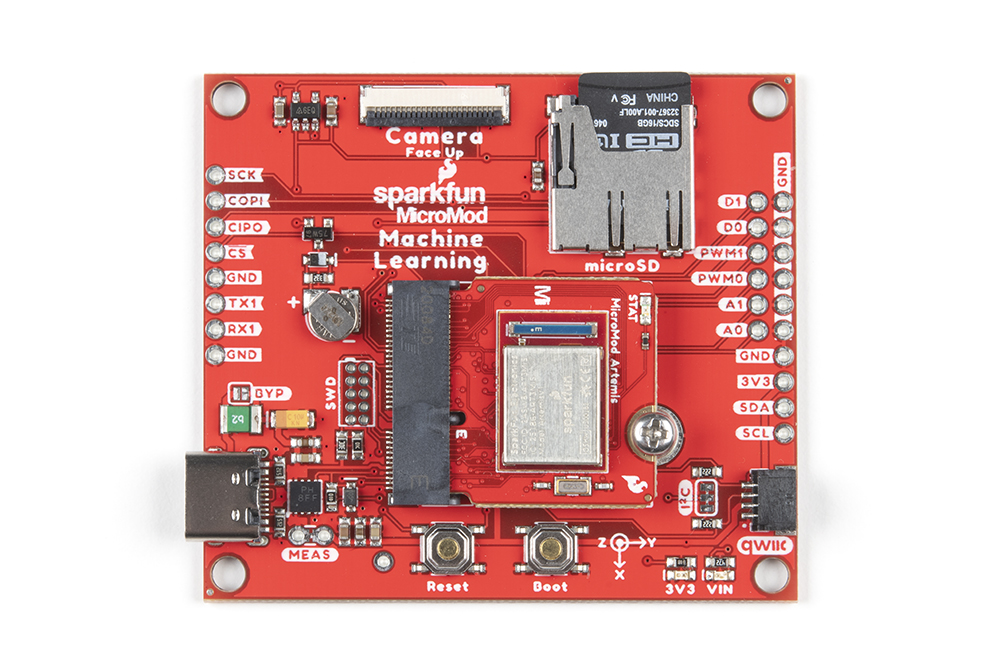
Once the board is secure, your assembled MicroMod system should look similar to the image below!
Connecting a Function Board to a Main Board
For those going the modular route with a Main Board, you will need a Processor and Function Board. The steps are similar to connecting a processor to a regular carrier board as explained above. Insert a Processor Board into the M.2 connector labeled as "Processor" at an angle of around 25°. Then secure the board using a Phillip's Head. Again, we recommend the classic SparkFun reversible mini-screw driver or the fancier pocket screw driver set but any #00, #0, or #1 Phillip's head driver will work.
 |
 |
| Processor Board Inserted at Angle | Processor Board Being Secured |
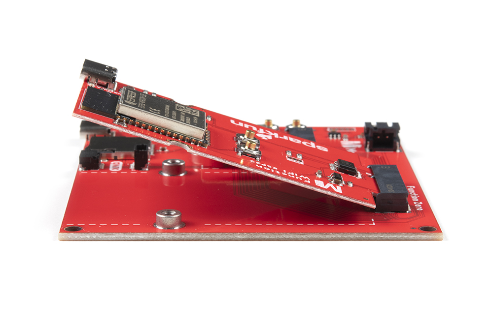
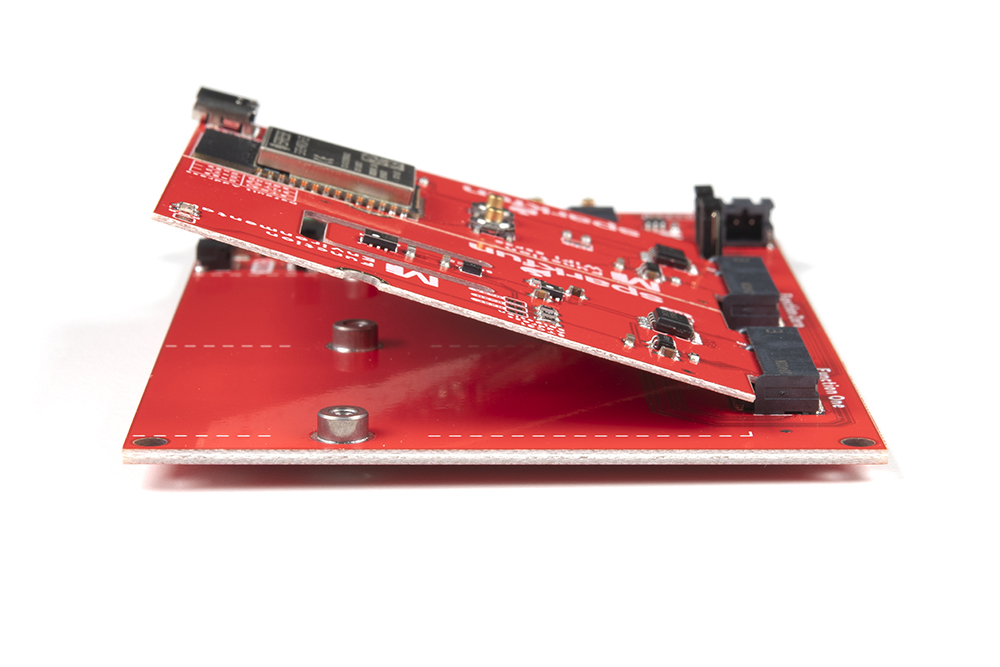
Then insert the Function Board at an angle (at around 25°) to the M.2 Connector labeled as "Function Zero" just like a Processor Board.
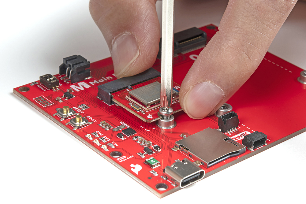
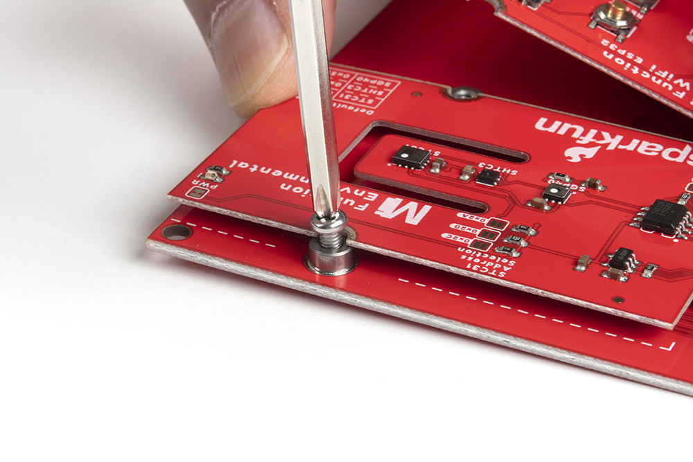
Once the board is in the socket, gently push down the MicroMod Function Board against the Main Board. Hold the Function board against the M.2 connector in place with your index finger and thumb. Then tighten one screw with a Phillip's head just enough to hold it in place. You'll want to avoid tightening the screw fully.

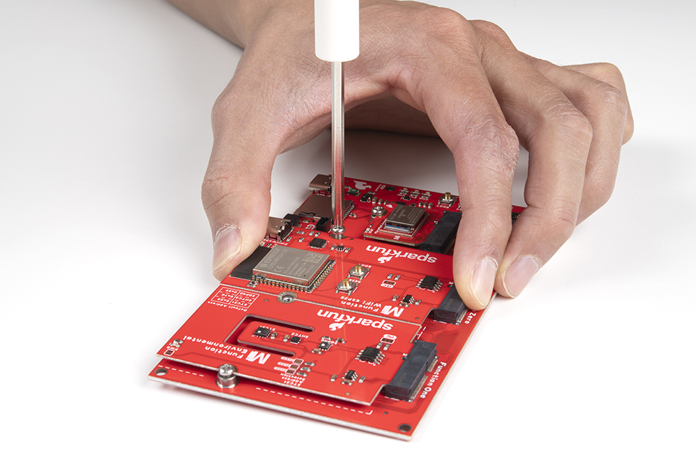
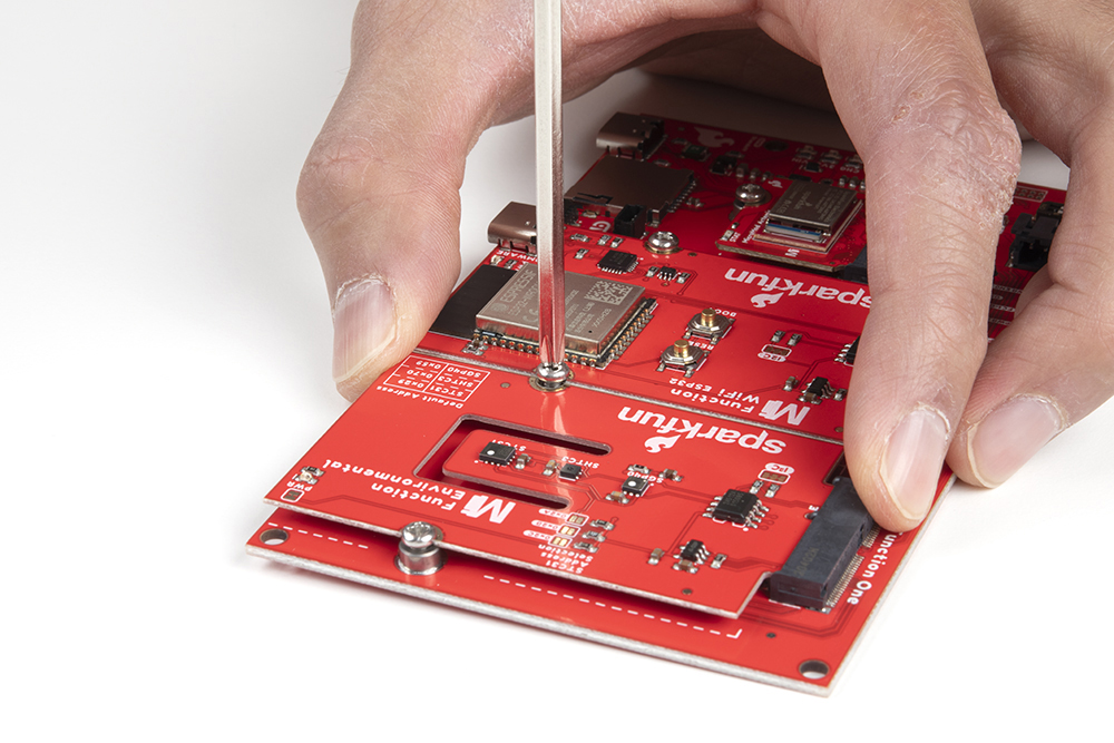
While still holding the Function Board in place, tighten the second screw on the other side to hold it in place. Go back and tighten both screws fully to ensure that the board is evenly held down.

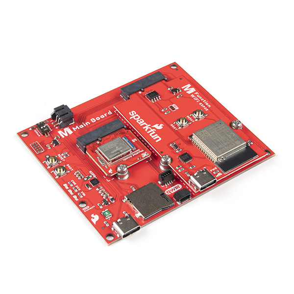
Once the boards are secure, your assembled MicroMod system should look similar to the image below!
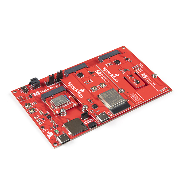
If you have a MicroMod Main Board - Double, the steps are the same as the Main Board - Single. The steps are similar to connecting a Processor and Function Board as explained above. Insert both Function Boards at an angle of around 25°.
Gently push down one of the Function Boards against the Main Board - Double. Hold the Function Board against the M.2 connector in place with your index finger and thumb. Then tighten one of the screws (avoid the middle screw between the two Function Boards) with a Phillip's head just enough to hold it in place. You'll want to avoid tightening the screw fully.
Gently push down the other Function Board against the Main Board - Double. Hold the Function Board in place while ensuring both boards are flush. Then tighten one of the screws (avoid the middle screw between the two Function Boards) with a Phillip's head just enough to hold it in place. You'll want to avoid tightening the screw fully
Tighten the middle screw while holding both Function Boards down. Go back and tighten all three screws fully to ensure that the boards is evenly held down.
Once the boards are secure, your assembled MicroMod system should look similar to the image below!
