Getting Started with the Artemis Development Kit
 Liquid Soulder, Member #1571936
Arduino Examples
Blink
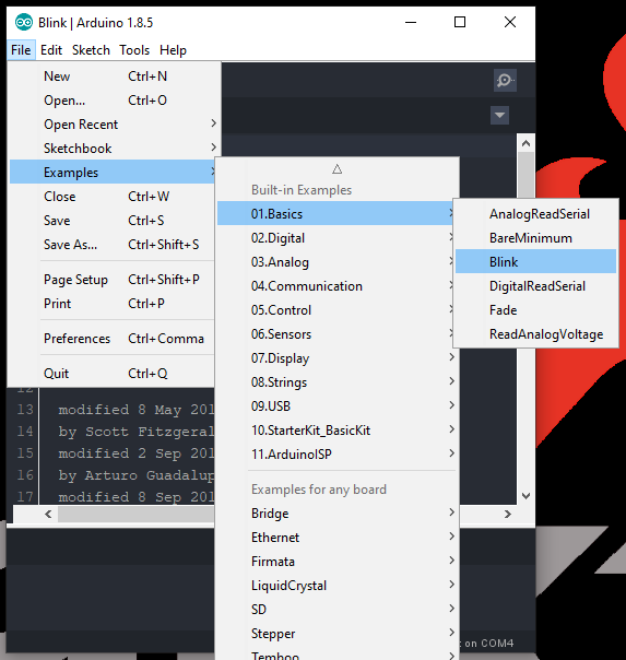
With full Arduino support, users will be able to implement the built-in examples of the Arduino IDE on the Artemis DK. To begin, let's start with the most basic example: Blink.
- From the drop down file menu, pull up the Blink sketch:
- Since users will need the compiled binary code in order to program the Artemis DK, save this example somewhere that is easily accessible; the desktop is a good option. (*Remember to use Save As, so that you retain the original example within the Arduino IDE.)
- Next, you will want to select the Artemis Dev Kit board from the tools drop down menu: Tools > Board: > Artemis Dev Kit
- Finally, you will need to acquire the compiled binary code using the sketch drop down menu: Sketch > Export compiled Binary (Ctrl + Alt + S)
- Now, the compiled binary will be located in the same location that the example was saved, from the previous step.
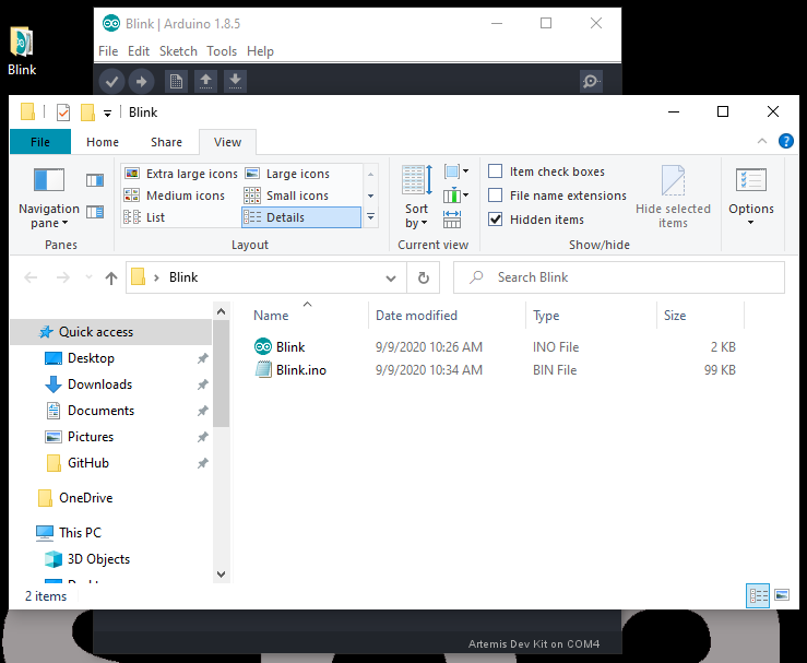
- All that is left is to drag and drop (or copy) the compiled binary file into the mass storage device for the Artemis DK. The interface chip will take care of the rest.
- The storage drive will automatically eject once the programming is complete. To verify that the board is working and that the programming was successful, users should see the
STATLED blinking in a ~1 sec. interval.
STAT LED blinking. (Click to enlarge) Hello World
In this example, users will create their own sketch, compile and export the binary file, program the Artemis DK, and view the serial communication in a terminal emulator. (*Most of the steps below are illustrated the procedure of the previous example.)
- Open a new sketch in the Arduino IDE from the drop down file menu: File > New.
Copy the example code below into the sketch:
language:c
// the setup routine runs once when you press reset:
void setup() {
  // initialize serial communication at 9600 bits per second:
  Serial.begin(9600);
}

// the loop routine runs over and over again forever:
void loop() {
  // print out "Hello World"
  Serial.println("Hello World");
  delay(500);
}
Save the sketch (File > Save As...) using the file drop down menu.
- Select the then, export the compiled binary code (Sketch > Export compiled Binary) using the sketch drop down menu.
- Drag and drop (or copy) the binary
.binfile into theARTEMISmass storage drive. The storage drive will automatically eject once the programming is complete. - To verify that the board is working and that the programming was successful, open a terminal emulator, such as TeraTerm or the Serial Monitor in the Arduino IDE. Connect to the serial port for the Artemis DK; don't forget to set the baud rate to 9600 bps.
Bluetooth: LED
Note: Users will need to download the NRF Connect app onto their phone. We highly recommend utilizing an Android phone as we have had difficulties with device connections in the app for Apple phones.
As in the prior examples, these steps will follow a similar procedure.
- From the drop down file menu, open the LED sketch: File > Examples > ArduinoBLE > Peripheral > LED.
- Save the sketch (File > Save As...) using the file drop down menu.
- Select the then, export the compiled binary code (Sketch > Export compiled Binary) using the sketch drop down menu.
- Drag and drop (or copy) the binary
.binfile into theARTEMISmass storage drive. The storage drive will automatically eject once the programming is complete. - To verify that the board is working and that the programming was successful, open a terminal emulator, such as TeraTerm or the Serial Monitor in the Arduino IDE. Connect to the serial port for the Artemis DK; don't forget to set the baud rate to 9600 bps.
- Click the reset button to begin the program. Users should see a
BLE LED Peripheralmessage in the terminal emulator. - Follow the steps and video below to control the
STATLED on the Artemis DK.- Unlock the phone and enable the Bluetooth.
- Open the NRF app.
- Click on the Scan button on the upper right corner.
- In the results, locate the device labeled
LED. Click on the CONNECT button to the right of the device name.- In the terminal emulator, users should see a
Connected to central:message followed by the mac address of the phone.
- In the terminal emulator, users should see a
- Once connected, locate the
Unknown Service. It will have the following service UUID:19B10000-E8F2-537E-4F6C-D104768A1214. - Click on the service. Then, locate and click on the upload button (up arrow).
- A dialog box will open. We want to write a value, so locate the
New Valuetext field, under the Write value drop-down menu option. Based on the control inputs to the LED, anLED onorLED offmessage will appear in the terminal emulator.- Enter
01to turn the LED on. Then click the SEND button. - Enter
00to turn the LED off. Then click the SEND button.
- Enter
Serial output of the
LED Bluetooth example. (Click to enlarge)
More Advanced Examples and Features
For more advanced examples and features of the Artemis DK with the Arduino IDE, check out the Arduino IDE software development tutorial. We also just released a blog post on streaming data over Bluetooth to a computer.
Artemis Development with Arduino
June 20, 2019
Additionally, since the Arduino core for the Artemis module is built upon the Mbed™ OS, the API can also be utilized within the Arduino IDE. For more information, check out the Mbed™ software development tutorial.