Getting Started with the AutoDriver
This Tutorial is Retired!
This tutorial covers concepts or technologies that are no longer current. It's still here for you to read and enjoy, but may not be as useful as our newest tutorials.
Contributors:
 SFUptownMaker
SFUptownMaker 
Hardware
The AutoDriver board is designed to be easily integrated into a project, even with multiple boards. Here's a brief tour of the hardware and how to connect it up.
The Board
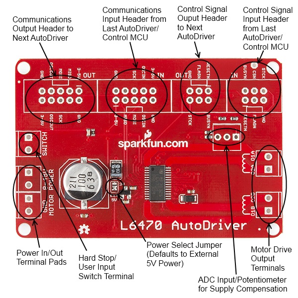
As you can see above, there are several connectors on the board. Let's take them one at a time:
- Communications in - where the SPI, clock, and logic level power enter the board. That can be either from the system CPU or from a prior AutoDriver board. By default, the AutoDriver expects a power supply input here, but that power supply is not the supply to the motors and should not exceed 5V. Designed for a 2x5 .1" shrouded connector, and to be connected by a 2x5 ribbon cable.
- Communications out - SPI, clock, and logic power out to the next AutoDriver. Designed for a 2x5 .1" shrouded connector, and to be connected by a 2x5 ribbon cable.
- Control signal in - metasignals for input and output to and from the AutoDriver. Chip select, optional step clock, and reset inputs come in here, and open-drain busy and error flag signals go back to the previous board. Designed for a 2x3 .1" shrouded header and to be connected by a 2x3 ribbon cable.
- Control signal out - passes the common control signals on to the next AutoDriver. Note that chip select is not passed from one board to the next; obviously we want only one board to be selected at a time. Designed for a 2x3 .1" shrouded header and to be connected by a 2x3 ribbon cable.
- Switch input - the L6470 can accept input from switches to provide for a hard-stop limit switch or a configurable user interrupt. We'll cover that later. Sized for a 3.5mm screw terminal.
- Power input - two connectors with two terminals each for power and ground to make connecting multiple boards to one power supply easy. This is the motor power input and is sized for a 3.5mm screw terminal.
- A and B winding outputs - the L6470 is designed to work with a bipolar stepper motor or a unipolar or universal stepper motor configured as a bipolar. One winding should be connected to each of these terminals, although it doesn't matter which winding connects to which terminal (other than to determine which direction is considered "forward").
- ADC input/potentiometer footprint - this footprint can be populated with a 200k potentiometer to provide for motor supply voltage correction, to ensure a constant drive current across varying supply voltages. Highly optional, but we put the footprint there, just in case.
An Example Connection to a RedBoard
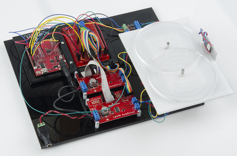
Later in this tutorial, we will show you how to hook up two AutoDriver boards to a RedBoard. For that example, you'll need two AutoDriver Boards along with the following: