Getting Started with the AutoDriver - v13
 SFUptownMaker
Test Hardware Assembly
Here's a step-by-step guide for assembling the parts used for the rest of the guide. If you have your own hardware, feel free to skip this part, but it's not a bad exercise to get you up to speed and make sure that your hardware is in a "known good" state before you begin writing code.
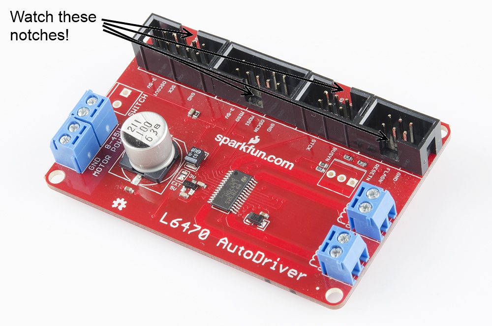
I'm going to take a few liberties with the basics here and assume that you're capable of assembling the RedBoard/Breadboard holder on your own, and that you can put the headers and screw terminal blocks on the AutoDriver boards without help. Pay attention to the orientation of the shrouded headers on the AutoDriver -- if you get them lined up properly, it'll help ensure that the signal routing through the ribbon cables is proper later on. Also note the single pin for the chip select, near the control signal in header. You'll need that later on.
I've also made a base plate to hold my AutoDriver boards in place; mine is fancy laser-cut acrylic, but you can hot glue the boards to a piece of cardboard or even just leave them loose, depending on your personal preferences and tool availability.
Assembling the ribbon cables
You can use pre-assembled ribbon cables, but, as we don't sell pre-assembled 6-conductor cables nor ribbon cables terminated in breadboard-friendly connections, I'm going to cover assembling the necessary cables here.
The easiest way to crimp the connectors to the end of the cable is to use a workbench vise; alternatively a pair of channel lock or vise-grip type pliers works well. In a pinch, you can use body weight and any flat surface; it takes quite a lot of pressure to push the connectors shut, however. Don't squeeze too hard, or you'll break the plastic.
Start by cutting your ribbon cable pieces. A pair of scissors works great for this, although it'll be rough on them, so don't use your sewing scissors! To keep our images concise, I'm using really short ribbons for these pictures. Feel free to make yours as long as necessary, although cables longer than a foot or two may cause signal integrity issues, which may affect the operation of your system.
Make sure that there are no little pieces of wire protruding from the end of the ribbon cable -- those can really ruin your day.
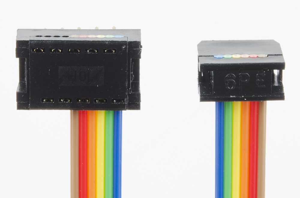
Now we need to crimp connectors onto the ends of each cable. We'll start with the breadboard-friendly ends; those are the hardest. Note that we're using the 2x5 connector for both the 10- and 6-conductor cables, since we don't sell a 2x3 breadboard-friendly end.
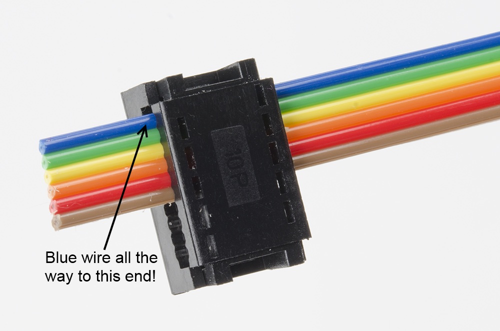
Insert the ribbon cable into the connector as shown below. For the 2x3, make sure that you've got the ribbon cable all the way to the top edge!
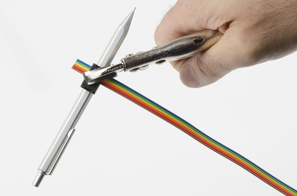
Before you apply pressure to crimp the connector closed, you need something to prevent the pins from being smashed in the process. A pencil fits between the pins perfectly.
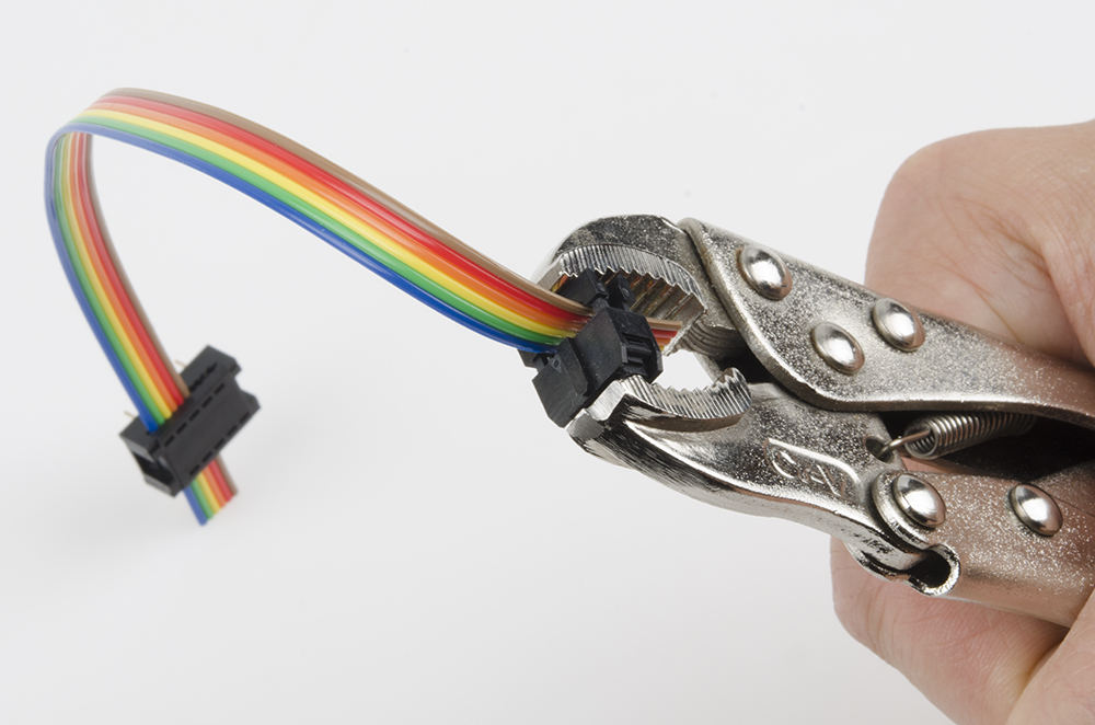
Next, we'll want to crimp on one of the other connectors. See the image below for proper orientation; crimping this in place is much easier because it doesn't have pins to be damaged.
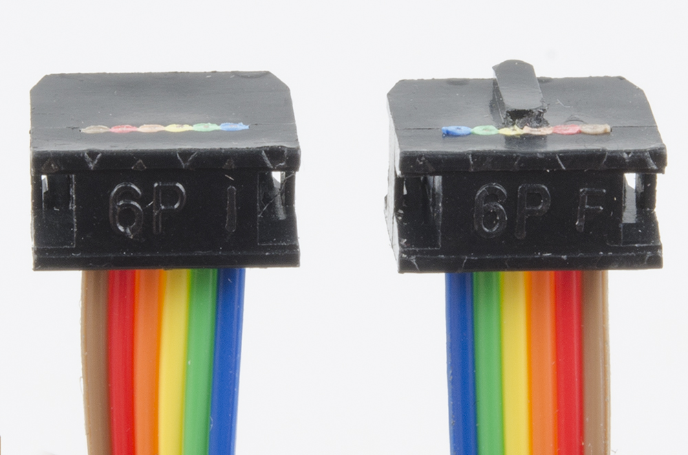
Finally, assemble the additional connectors to the ends of the other ribbon cables, as shown below. Orientation of the connector is important, as the keying on the shrouded headers forces them into the proper orientation only if the cables are assembled right!
Wiring up the stepper motors
As mentioned earlier, there are two screw terminals on the board for connecting the motor. Each one should have one coil of the motor connected to it; if you're not sure of how your stepper motor's wires are connected, you can use a multimeter to figure it out. Two wires connected to the same coil should show a very low resistance (on the order of a few ohms) between them.
Once you've identified the pairs of wires, connect one pair to the 'A' screw terminal and the other to the 'B' screw terminal. The order of the wires isn't terribly important yet, as the order determines the direction in which the motor turns, not whether it turns or not.
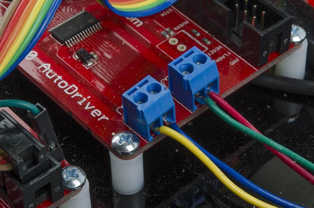
The above picture shows the order I've selected for our medium stepper motors. It's probably a good idea to use the same wire order on both boards, so the relative direction of both motors is the same. If you need the direction to be opposite for the two motors (say, to drive the wheels of a robot), you can simply reverse the order of one pair of wires.
Connecting the boards
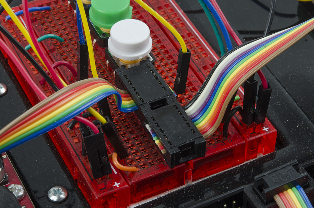
If all your ribbon cables are properly assembled, the rest of this should be a snap. Start by inserting the breadboard-friendly ends into the breadboard. You'll be making connections on both sides of the connector, so it helps to pre-bend the ribbon to a right angle with the breadboard.
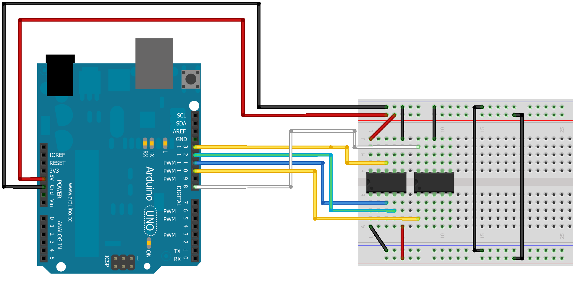
Here's a little wiring diagram of how the connections to the breadboard connectors should be made from the RedBoard or Arduino.
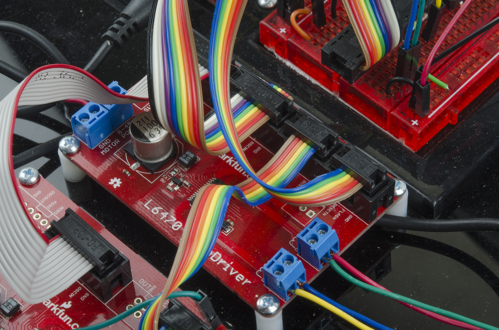
That's the hardest part. Now all you need to do is connect the ribbon cables to the AutoDriver boards.
Connecting the Power Supply
Finally, connect up the power. All you need is a four pieces of hookup wire with bared ends. Here's a picture of the power connections all wired up:

It's generally a good idea to hook up the power to the RedBoard and logic circuitry before you power the AutoDrivers; do note that you can't access the AutoDriver boards via SPI until BOTH parts are powered, however.