Getting Started with the Autonomous Kit for the Sphero RVR
Examples
Keyboard ⌨️ Control & Camera Web Interface
This example will focus on getting the Keyboard ⌨️ Control example from the Sphero SDK working while streaming the Raspberry Pi's camera video feed. (*For more details on the Keyboard ⌨️ Control example, check out Sphero's webpage.)
To begin, users should remotely access the Raspberry Pi through the SSH protocol (see the Remote Access with SSH section).
Enabling the Camera
Once users have logged in, change the current working directory to the RPi_Cam_Web_Interface folder using the following command:
cd RPi_Cam_Web_Interface
Once inside the RPi_Cam_Web_Interface folder, users can utilize the following two commands to enable/disable the web service for the camera and pan-tilt servo controls.
- To enable the camera and servo controls, use the
./start.shcommand. - To disable the camera and servo controls, use the
./stop.shcommand.
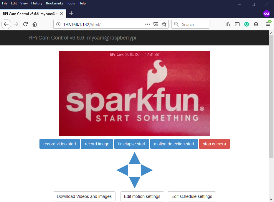
After the web service is enabled, users can bring up a live stream of the video feed from the camera using a web browser on the remote computer. The url for the web interface is: <IP Address>/html (users can also use raspberrypi.local/html). If the url doesn't work, try adding the http:// prefix (eg. http://raspberrypi.local/html/).
Users should then return to the home directory using either the cd ~ or cd .. command.
Keyboard Control
Note: Don't forget to move the serial switch on the Pi Servo pHat to RVR so that the serial communication passes through the 4-pin UART header for the Sphero RVR.
Move serial switch to
RVR. (Click to enlarge)
Next, to begin using the Sphero SDK, users should change the current working directory to the sphero-sdk-raspberrypi-python folder using the following command:
cd sphero-sdk-raspberrypi-python
Once inside the sphero-sdk-raspberrypi-python folder, users will need to spawn a shell in a virtual environment using the pipenv shell command (this will create a virtual environment if one doesn't already exist). This is the most important step to "initializing" the Sphero SDK; otherwise, users will run into issues executing any of the examples.
After the shell has been activated, users should move the current working directory to the keyboard_control folder using the following command:
cd projects/keyboard_control
Once inside the keyboard_control folder, users will need to start the drive_with_wasd_keys.py Python example code with the following command:
python3 drive_with_wasd_keys.py
You may see a few initialization printouts like:
Checking RVR firmware versions...
Checking CMS firmware versions...
Firmware check done.
Wait a minute or two for the script to finish initializing. Once complete, users should be able to use the W, A, S, D, and Space Bar keys to control the Sphero RVR.
Have fun driving the RVR around, don't forget to play with the servo controls on the web interface.
Exiting
Use Ctrl+C to interrupt the keyboard control script. The example code will then display:
Keyboard Interrupt...
Press any key to exit.
and prompt user to Press any key to exit.. Pressing another key will exit the script. To exit the virtual environment shell, type exit or Ctrl+D.
To disable the web interface, change back to the RPi_Cam_Web_Interface directory and use the ./stop.sh command.
Using Both VL53L1X Sensors
To use both VL53L1X ToF sensors, users will need to use the Qwiic Mux to access a single sensor and change the I2C address. Then users will need to access both sensors through the Qwiic Mux to retrieve the distance data. The following instructions will get users started on this process with the included example code.
To begin, users should remotely access the Raspberry Pi through the SSH protocol (see the Remote Access with SSH section).
Changing the I2C Address
The VL53L1X ToF distance sensor has a "software" configurable I2C address; however it is "volatile", upon re-powering the device, it will automatically reset to the default I2C address. This is where the Qwiic Mux comes in. It is used to isolate the sensors, initially, so that the I2C address of one of the sensors can be reconfigured on power up.
Once logged in, change the current working directory to the sparkfun_autonomous_kit folder.
- Users can use
cd sparkfun_autonomous_kitfrom thehomedirectory. - Otherwise, user can also
cd ~/sparkfun_autonomous_kitfrom any other location.
Inside the sparkfun_autonomous_kit directory is the vl53l1x_change_i2c_address.py example code. Execute the example code.
- Use the
lscommand list the files in the directory and to verify it is there. - To execute the example code, run
python3 vl53l1x_change_i2c_address.py.
Follow the prompts of the example code. When selecting which channel on the Mux to enable, select one of the channels that the VL53L1X ToF distance sensor is attached to (i.e. either channel 0 or 4). If users have successfully performed the I2C address change, they should be able to test the sensor on the new I2C address. Use Ctrl+C to terminate the script.
Note: The entries to the prompts in the .gif above are: y, y, y, y, 0, 41, 85, and y.
Update: The Assembly Guide has been modified to use channels 3 and 4 on the Qwiic Mux. Users can either move the cable (i.e. from channel 3 to channel 0) or modify the entries into the prompts (i.e. enter 3 instead of 0).
Running the Example Code
Now that users have modified the I2C address of one of the sensors, they can use the example code to get readings from both sensor.
Inside the sparkfun_autonomous_kit directory is the hardware_pre_test folder. Change the current working directory to the hardware_pre_test folder.
- Use the
cd hardware_pre_testcommand.
Inside the hardware_pre_test directory is the VL53L1X folder. Change the current working directory to the VL53L1X folder.
- Use the
lscommand list the files in the directory and to verify it is there. - Use the
cd VL53L1Xcommand.
Inside the VL53L1X directory is the dual_sensors.py example code. Execute the example code.
- Use the
lscommand list the files in the directory and to verify it is there. - To execute the example code, run
python3 dual_sensors.py.
Follow the prompts of the example code. When selecting, which channel on the Mux to enable, select both of the channels that the VL53L1X ToF distance sensors are attached to (i.e. channels 0 and 4). If users have successfully performed the I2C address change, they should be able to designate the I2C address of the front and rear sensors. Once users are finished testing, use Ctrl+C to terminate the script.
Note: The entries to the prompts in the .gif above are: y, y, y, 0, y, 41, n, 85, and 41.
Update: The Assembly Guide has been modified to use channels 3 and 4 on the Qwiic Mux. Users can either move the cable (i.e. from channel 3 to channel 0) or modify the entries into the prompts (i.e. enter 3 instead of 0).