Getting Started with the Autonomous Kit for the Sphero RVR
Hardware Overview
For a brief overview of each component, check out the product videos; otherwise, for a more in-depth look at their operation, check out their hookup guides.
Raspberry Pi Zero W (with Headers)
The Raspberry Pi Zero W is the brains of this kit. The Raspberry Pi Zero W is a single board computer (SBC), with WiFi and Bluetooth connectivity, and a CSI camera interface. Below is an annotated image, highlighting components of the hardware that users will want to be familiar with.
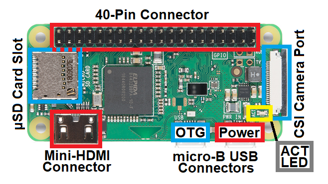
Getting Started with the Raspberry Pi Zero Wireless
July 13, 2017
Pi Camera (v2)
The Pi Camera is the eyes of this kit. With a 8MP sensor, the camera module can be used to take high-definition video, as well as still photographs. Below is an annotated image, highlighting components of the hardware that users will want to be familiar with. Primarily, users should note that the contacts on the ribbon cable face towards the image sensor.
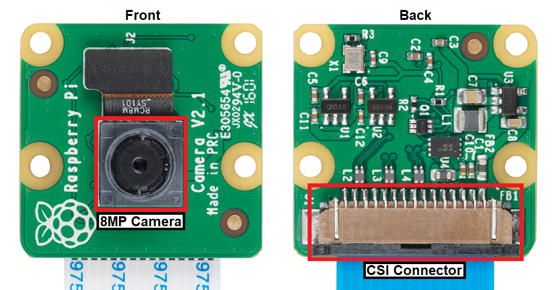
Setting Up the Pi Zero Wireless Pan-Tilt Camera
September 14, 2017
Pi Servo pHat
The Pi Servo pHat is the heart or body of this kit. Excluding the Pi Camera, it interfaces between the Raspberry Pi Zero W and the rest of the hardware included in this kit. Below is an annotated image, highlighting components of the hardware that users will want to be familiar with.
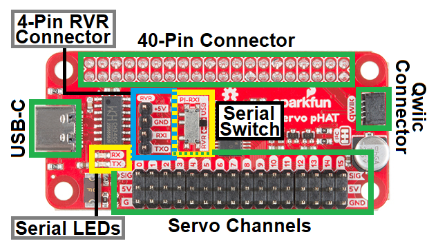
Users should note the position of the serial switch when using the Sphero RVR. Special care should also be taken when connecting the serial UART cable from the Sphero RVR or the servo cables to the Pi Servo pHat. Neither of these connections are polarized and can be easily connected in reverse. The silk screen on the board labels the proper pin connections.
Pi Servo pHAT (v2) Hookup Guide
July 11, 2019
Pan-Tilt Servos
The pan-tilt servo assembly is the neck of the kit, for panning and tilting the Pi Camera. The servos control the orientation of the bracket assembly. Below is an annotated image, highlighting wiring of the hardware that users should be familiar with.
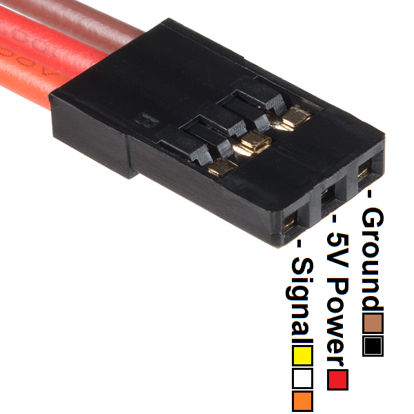
Users should note that the wiring harness (sleeving) may come in a variety of color combinations. The image, above, illustrates the more commonly used colors. (*For more details, check out our hobby servo tutorial.)
Setting Up the Pi Zero Wireless Pan-Tilt Camera
September 14, 2017
GPS (Titan X1) Module
The GPS module is the geospatial awareness of the kit. Once a lock is acquired, the Titan GPS receiver is able to determine its location to within a 3m radius. Below is an annotated image, highlighting components of the hardware that users will want to be familiar with.
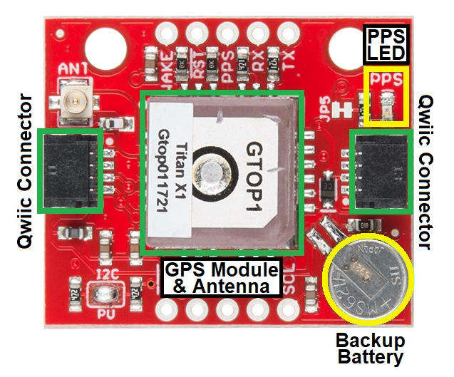
Users should note that the PPS LED can be used as a general indicator for when a satellite lock is initially established. Additionally, the GPS module primarily only works when it has a direct view of the sky (i.e. outside; not through a window), to receive satellite signals. (*For more details on GPS receivers, check out our GPS basics tutorial.)
SparkFun GPS Breakout - XA1110 (Qwiic) Hookup Guide
October 19, 2017
ToF (VL53L1X) Distance Sensors (Advanced Kit Only)
The ToF sensors provide an additional level of geospatial awareness for the kit. The sensor uses IR laser pulses to detect possible obstacles in front of the sensor. Below is an annotated image, highlighting components of the hardware that users will want to be familiar with.
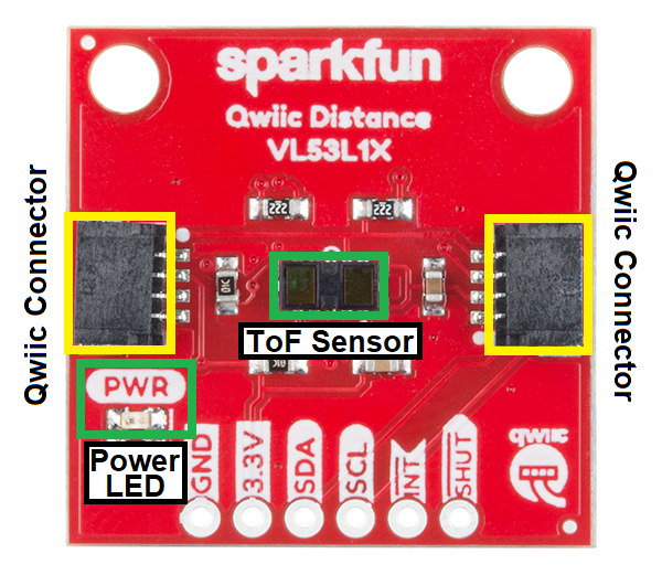
Users should note that ToF sensors do have performance limitations. For example, the sensor FOV, the target properties (i.e. size, color, reflectivity, etc.), and the ambient light all affect the sensor performance and reliability. (*For more details, check out these related product support articles from Garmin: How the Garmin LIDAR-Lite Products Work with Reflective Surfaces and Effects of distance, target size, aspect, and reflectivity on LIDAR-Lite v3/v3HP returned signal strength .)
Additionally, the product brochure for the VL53L1X ToF module lists that laser beams are safe enough that eye protection is not required. However, we still recommend users avoid staring into the sensor module (or beam path) anyway. (*For more details on the VL53L1X, check out the datasheet.)
Qwiic Distance Sensor (VL53L1X, VL53L4CD) Hookup Guide
February 10, 2022
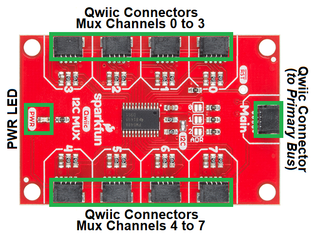
Qwiic Mux (TCA9548A) (Advanced Kit Only)
The mutiplexer (mux) is a simple switch control device for the I2C bus. This component allows users to access the VL53L1X ToF sensors individually, as they share the same I2C address on power up. Below is an annotated image, highlighting components of the hardware that users will want to be familiar with.
Qwiic MUX Hookup Guide
July 19, 2018
Sphero RVR
The Sphero RVR is a third-party product that is used as a vehicular platform (or legs) for the SparkFun Autonomous Kits. The primary interface for these kits is the 4-pin serial UART connection on the Sphero RVR. However, users can also operate the Sphero RVR with a mobile device through Bluetooth with the Sphero EDU app.


On the front, "port" side of the Sphero RVR, there is the 4-pin serial UART connector and USB port. There is a clear plastic lid covering these connections which users will need to open. Users should also note the arrangement of the pin connections, as labeled on the printed circuit board (PCB) behind the clear cover.