Getting Started with the Autonomous Kit for the Sphero RVR
Initial Hardware Tests
This section contains instructions for testing all the hardware in the kit to verify that everything is working. These are individualized tests for the hardware which can be used to help troubleshoot these devices later on. It is recommended that users test components individually (as laid out in this section) to reduce the number of unknown variables.
Raspberry Pi
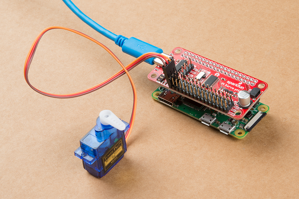
The first component to test is the Raspberry Pi. Assemble the Raspberry Pi, Pi Servo pHat, and SD card as shown below. Users can power the device either through the 4-pin connector or the USB-C connector on the Pi Servo pHat.
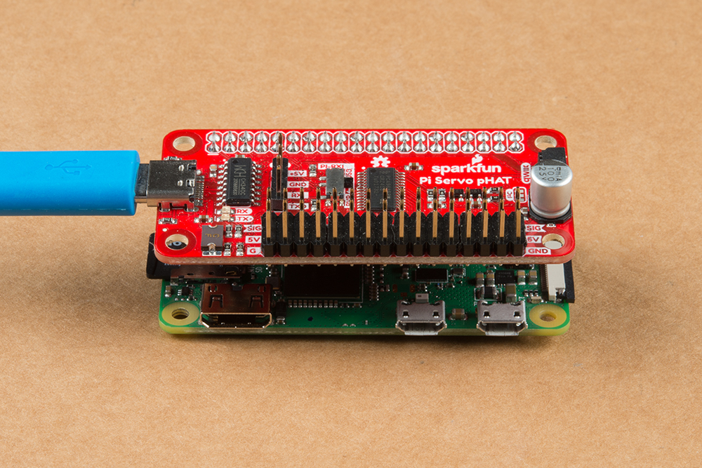
It should power on, boot, connect to the WiFi network (configured previously), and be accessible through the SSH protocol when working properly.
Power and Boot
Once powered, you should see a green LED turn on. While the Raspberry Pi Zero W is booting, the green LED will flash indicating that the SD card is being accessed.

WiFi Network Connection
It will take a minute or two for the Raspberry Pi to finish booting and connect to the WiFi network. Once connected to the WiFi network, the Raspberry Pi can either be pinged or mapped from another computer (on the same network). The simplest method is to ping the Raspberry Pi using the following command in your Terminal or Command Prompt. Users that have the IP address of the Raspberry Pi should ping that IP address; otherwise, if users have forgotten or used the SD card method, they can ping the domain name raspberrypi.local. The limiting factor to using the domain name, is that only ONE Raspberry Pi can be on the network at a time; otherwise, users will run into contention issues and will likely connect to the wrong Raspberry Pi.
ping <IP ADDRESS>orping raspberrypi.local
(*More information on determining the Raspberry Pi's IP address can be found on the Raspberry Pi Foundation's website.)
SSH Access
Once users have pinged the Raspberry Pi and verified that it is connected to the network, they can access it remotely through the SSH protocol. On a modern computer OS, this can be done through the Terminal or Command-Prompt. However, users with more outdated systems will need to use an SSH client like Putty (see the Headless Raspberry Pi Setup tutorial). Using the Command-Prompt or Terminal, enter the following command:
ssh pi@<IP ADDRESS>orssh pi@raspberrypi.local
Again, if users have forgotten the IP address or used the SD card method, they can ping the domain name raspberrypi.local (the same limiting factor applies regarding the number of Raspberry Pis connected to the network).
Once connected, users will be prompted to login. If the login prompt doesn't show up after few moments, press the Enter or Return key to bring up the login prompt. The username and password are the default for the Raspberry Pi: Username = pi (used in ssh command) and Password = raspberry.
-
For users creating a new SSH connection, there may also be an authentication prompt. Type
yesto continue.The authenticity of host '[IP Address]' can't be established. ECDSA key fingerprint is SHA256: [Bunch of numbers and letters]. Are you sure you want to continue connecting (yes/no)? -
To retrieve the IP address of the Pi, once users are connected, use the
ifconfigorhostname -Icommands as mentioned in the Software Overview: Part 1 - Raspbian OS section.
Once users have remotely accessed the Raspberry Pi, the test is complete. Shutdown the Raspberry Pi using the sudo shutdown now command as mentioned in the Software Overview: Part 1 - Raspbian OS section. (*Remember... before unplugging the power or removing the SD card, be sure to verify that the Raspberry Pi has completely shutdown to avoid corrupting the SD card.)
 Shutting down the Raspberry Pi. (Click to enlarge)
 ACT LED indicating the end of the power down sequence, right before the power can be disconnected. (Click to enlarge)
Pi Camera & Camera Web Interface
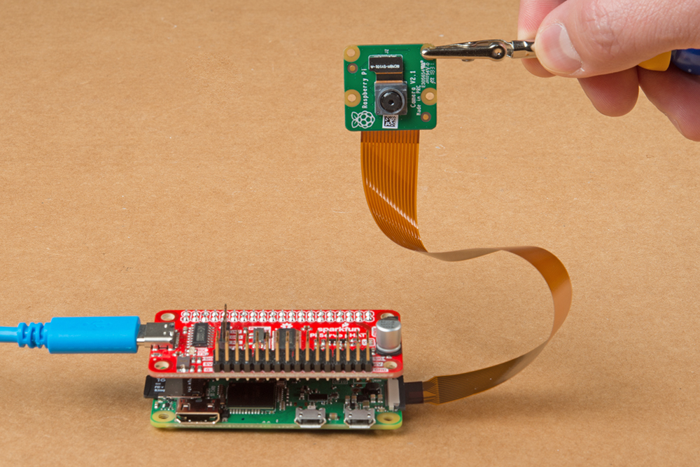
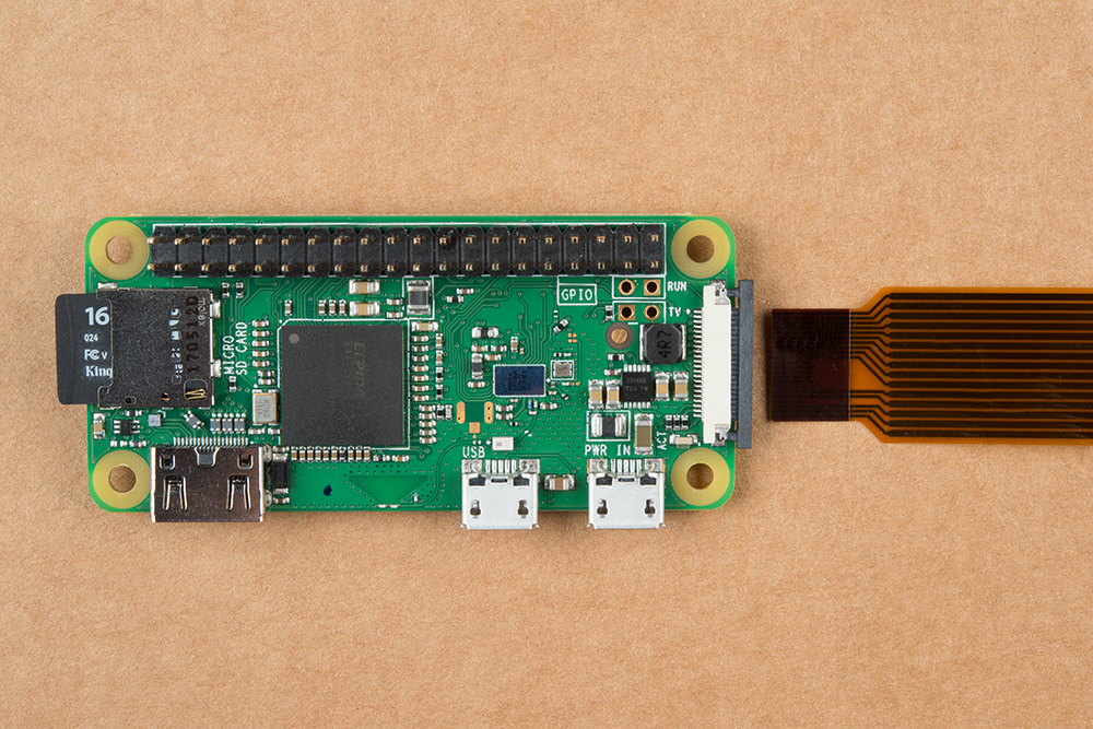
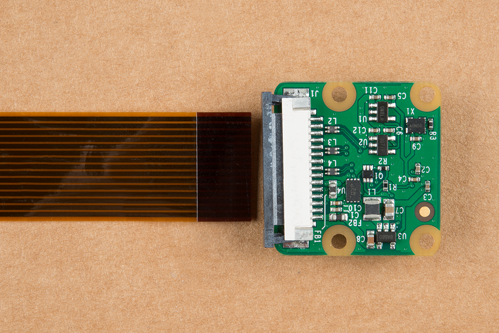
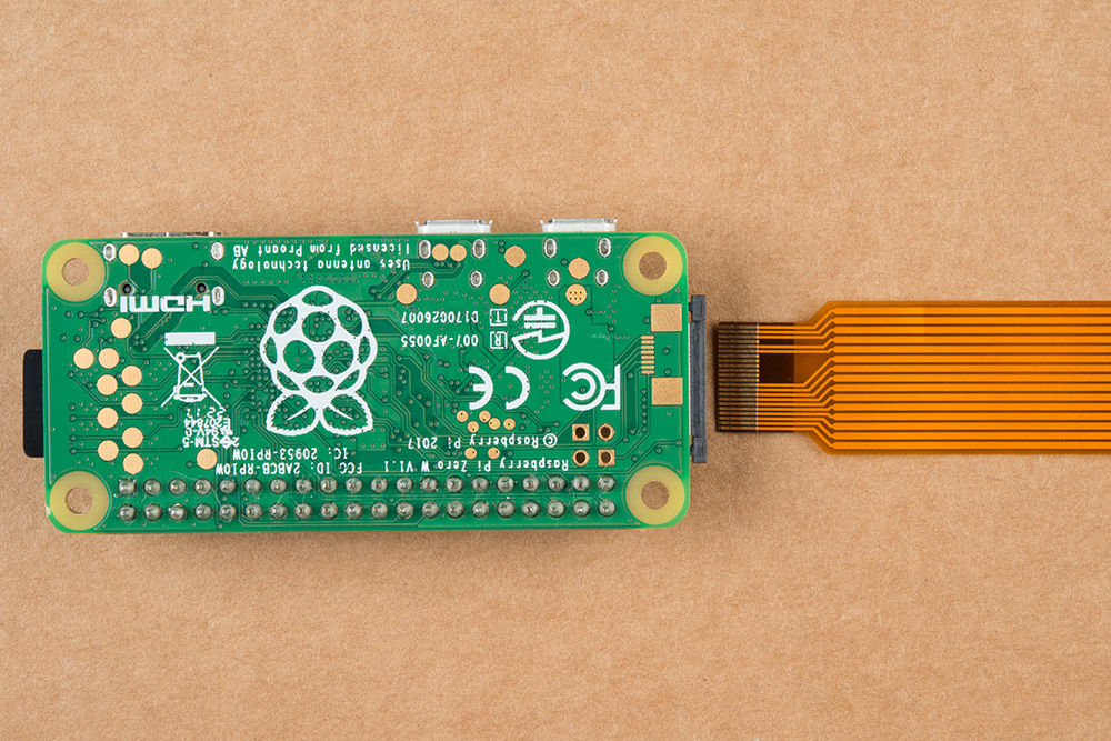
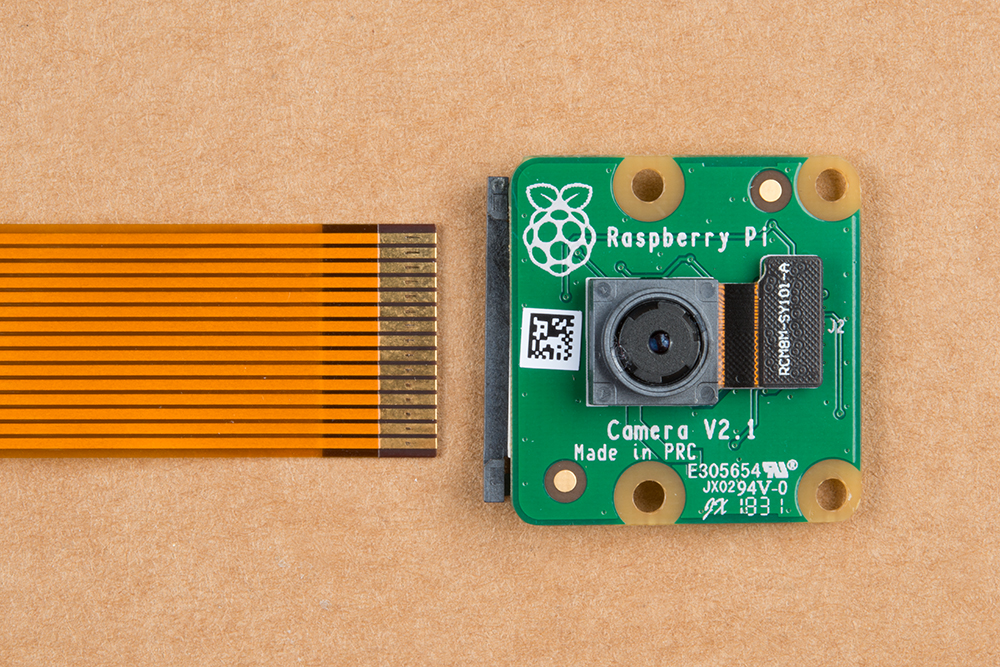
Once users have verified that the they can remotely access the Raspberry Pi, it is time to test the Raspberry Pi camera web interface. Connect the Raspberry Pi camera to the Raspberry Pi Zero W as shown below (take note of what side the gold contacts are on).

Once the camera is connected and the Raspberry Pi is powered on (via the Pi Servo pHat), wait for the Raspberry Pi to finish booting and connecting to the WiFi network. Then, remotely access the Raspberry Pi using the SSH protocol from another computer and login.
Once logged in, users will want to test the Pi Camera web interface.
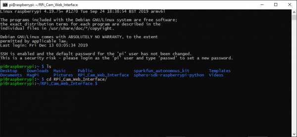
Change the current working directory to the
RPI_Cam_Web_Interfacefolder.- Users can use
cd RPI_Cam_Web_Interfacefrom thehomedirectory. - Otherwise, user can also
cd ~/RPI_Cam_Web_Interfacefrom any other location.
 Change the directory to the
RPI_Cam_Web_Interfacefolder. (Click to enlarge)- Users can use
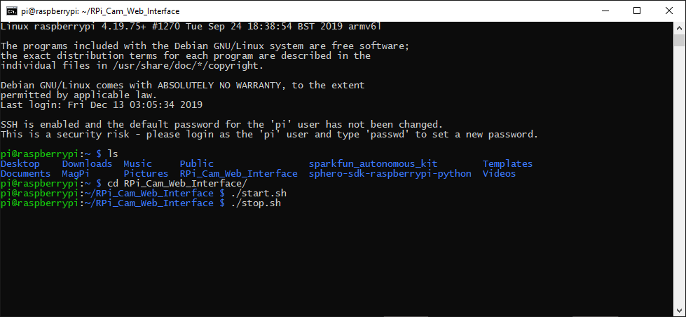
- Initializing and terminating the web camera interface is simple. Below are the two available commands to use once users are in the
RPI_Cam_Web_Interfacedirectory:./start.sh- Start the Camera./stop.sh- Stop the Camera
Use
./start.shto initialize the stream for the video feed from the Pi Camera. Start the video feed from the Pi Camera to the web interface. (Click to enlarge)
- While the web camera interface is running, pull up a web browser with enter the following URL:
<IP ADDRESS>/html. (Again, if users have forgotten the IP address or used the SD card method, they can use the domain nameraspberrypi.localin place of the<IP address>.) Users should see something similar to the images below.


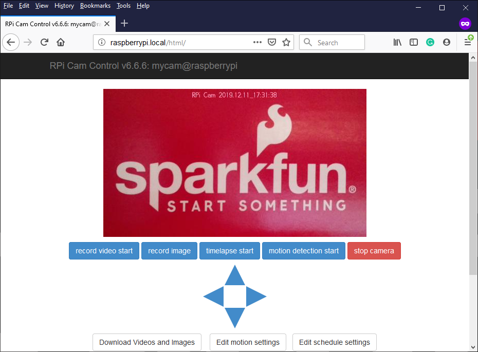
- Users should be able to see the video feed from the Pi Camera on the webpage.
Once users are finished testing the Pi Camera, use
./stop.shto terminate the video feed. End the video feed from the Pi Camera to the web interface. (Click to enlarge)
Once video feed is terminated, shutdown the Raspberry Pi using the sudo shutdown now command as mentioned in the Software Overview: Part 1 - Raspbian OS section. (*Remember... before unplugging the power or removing the SD card, be sure to verify that the Raspberry Pi has completely shutdown to avoid corrupting the SD card.)
Shutting down the Raspberry Pi. (Click to enlarge)
ACT LED indicating the end of the power down sequence, right before the power can be disconnected. (Click to enlarge)
Pi Servo pHat
The Pi Servo pHat plays a central roll for connecting everything to the Raspberry Pi. After testing the Raspberry Pi above, users should have already verified that power is being passed through the Pi hat (pHat). This section will focus on the servo control of the Pi Servo pHat; the following Qwiic Devices section will verify the I2C functionality through the pHat.
Qwiic Test
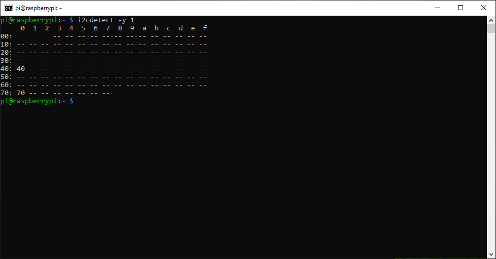
Although the Pi Servo pHat isn't actally a Qwiic device, the servo controller IC does use the I2C bus. A simple test to verify that it is responding is to use the i2cdetect -y 1 command to ping the I2C bus. By default, the servo controller IC should be at the 0x40 I2C address. If the general call address is enabled, the 0x70 I2C address may appear as well.
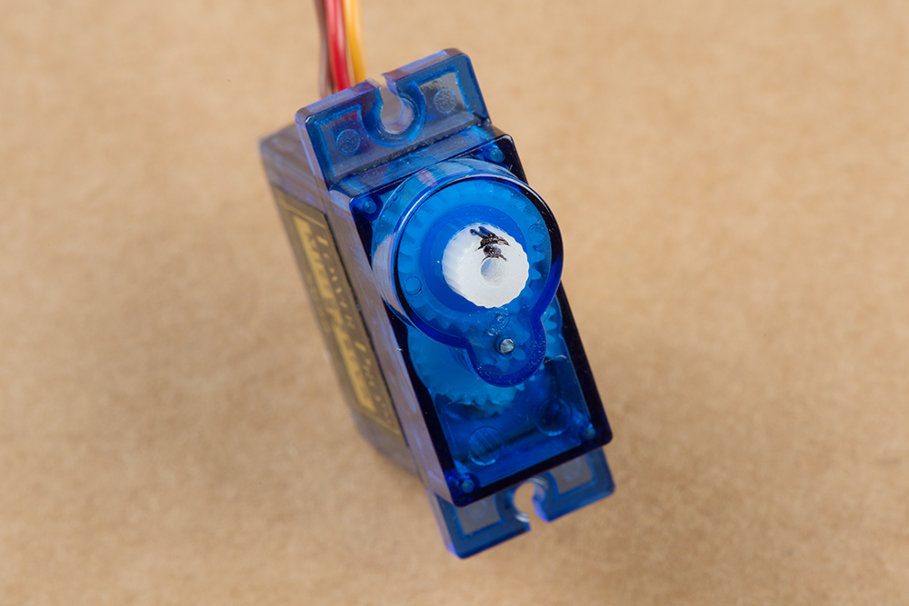
Servo Test
This test will verify that the Pi Servo pHat can control the servos and that the servos are functioning properly. Additional instructions are also provided below to assist in pre-alignment of the pan-tilt servos prior to assembly. This will help to avoid damaging the servo on their inaugural operation as well as streamline the assembly process.
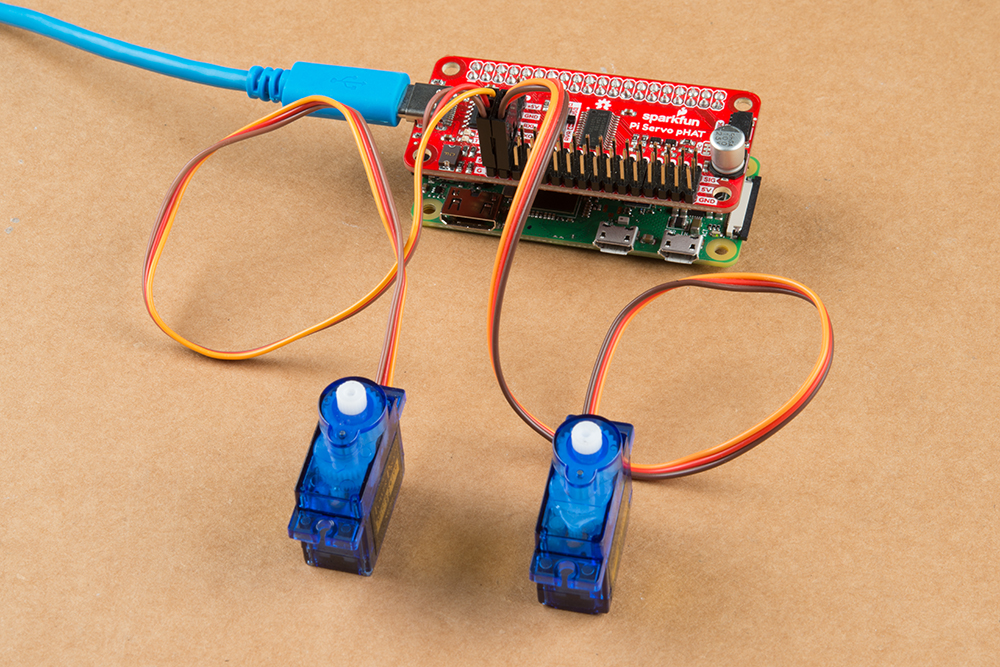
Users will need to assemble the Raspberry Pi Zero W with the Pi Servo pHat and attach a servo to Channel 0. Double check that the wiring is aligned properly.

Once the everything is assembled and the Raspberry Pi is powered on, wait for the Raspberry Pi to finish booting and connecting to the WiFi network. Then, remotely access the Raspberry Pi using the SSH protocol from another computer and login.
Once logged in, users will want to run the servo example code.
Change the current working directory to the
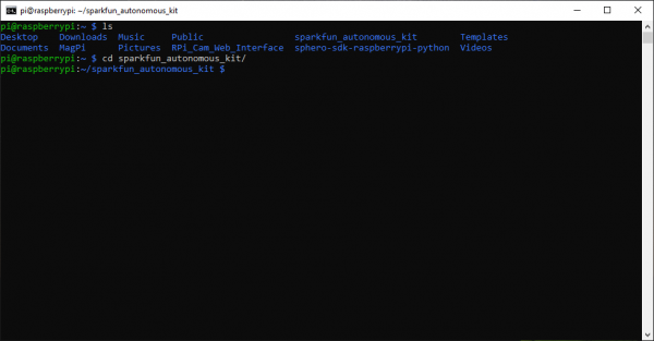
sparkfun_autonomous_kitfolder.- Users can use
cd sparkfun_autonomous_kitfrom thehomedirectory. - Otherwise, user can also
cd ~/sparkfun_autonomous_kitfrom any other location.
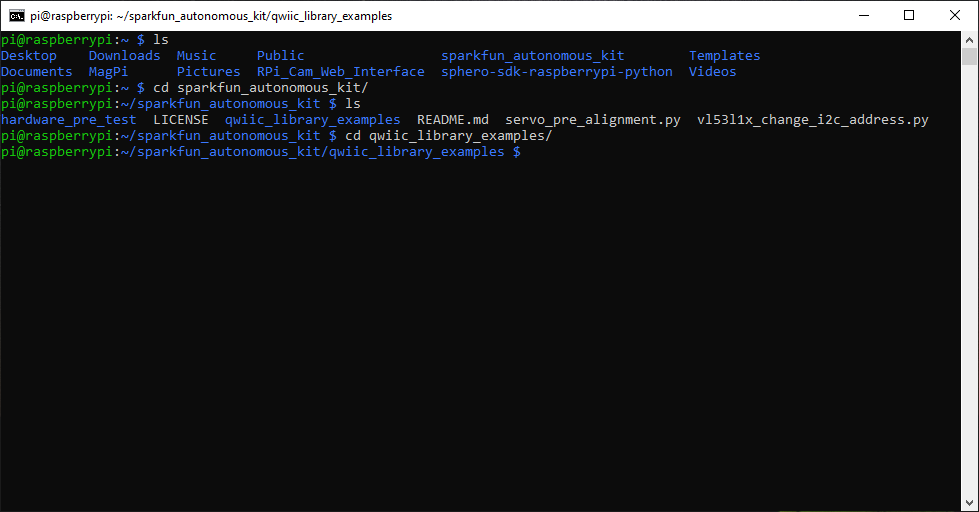
 Change the directory to the
sparkfun_autonomous_kitfolder. (Click to enlarge)- Users can use
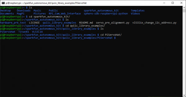
Inside the
sparkfun_autonomous_kitdirectory is theqwiic_library_examplesfolder. Change the current working directory to theqwiic_library_examplesfolder.- Use the
lscommand list the files in the directory and to verify it is there. - Use the
cd qwiic_library_examplescommand.
 Change the directory to the
qwiic_library_examplesfolder. (Click to enlarge)- Use the
Inside the
qwiic_library_examplesdirectory is thePiServoHatfolder. Change the current working directory to thePiServoHatfolder.- Use the
lscommand list the files in the directory and to verify it is there. - Use the
cd PiServoHatcommand.
 Change the directory to the
PiServoHatfolder. (Click to enlarge)- Use the
Inside the
PiServoHatdirectory is theex1_full_sweep_with_90_deg_servo.pyexample code. Execute the example code.- Use the
lscommand list the files in the directory and to verify it is there. - To execute the example code, run
python3 ex1_full_sweep_with_90_deg_servo.py.
 Execute the
ex1_full_sweep_with_90_deg_servo.pyexample code. (Click to enlarge)- Use the
- If it is working properly, users should see the servo moving back and forth. It may be helpful to attach one of the servo horns to verify that the swing range is ~90°. Once users are finished testing, use Ctrl+C to terminate the script.


- Shutdown the Raspberry Pi using the
sudo shutdown nowcommand as mentioned in the Software Overview: Part 1 - Raspbian OS section. Then, swap the servos. (*Remember... before unplugging the power or removing the SD card, be sure to verify that the Raspberry Pi has completely shutdown to avoid corrupting the SD card.)- Users should shutdown and unplug the Raspberry Pi before swapping the servos.
- Hot swapping the servos (swapping the servos while the Raspberry Pi is powered) can create a power failure issue, which could possibly corrupt the SD card.
Shutting down the Raspberry Pi. (Click to enlarge)
ACT LED indicating the end of the power down sequence, right before the power can be disconnected. (Click to enlarge)
- Repeat the process to test the other servo.
- To jump directly to the
PiServoHatdirectory:- Users can use
cd sparkfun_autonomous_kit/qwiic_library_examples/PiServoHatfrom thehomedirectory. - Otherwise, user can also
cd ~/sparkfun_autonomous_kit/qwiic_library_examples/PiServoHatfrom any other location.
- Users can use
- To jump directly to the
That completes the Pi Servo pHat hardware test, shutdown the Raspberry Pi using the sudo shutdown now command as done previously. Users can choose to pre-align their servos (recommended) or move on to testing the Qwiic devices.
Aligning Servos (Optional)
To help users avoid damaging their servos for the pan-tilt bracket, an example pre-alignment code has been provided. The example code will align the pan (or horizontal movement) servo at 45° and the tilt (or vertical movement) servo at 37°. To pre-align the servos, users will need to assemble the Raspberry Pi Zero W with the Pi Servo pHat and two servos.
Once everything is assembled and the Raspberry Pi is powered on, wait for the Raspberry Pi to finish booting and connecting to the WiFi network. Then, remotely access the Raspberry Pi using the SSH protocol from another computer and login.
Once logged in, users will want to run the servo pre-alignment example.
Change the current working directory to the
sparkfun_autonomous_kitfolder.- Users can use
cd sparkfun_autonomous_kitfrom thehomedirectory. - Otherwise, user can also
cd ~/sparkfun_autonomous_kitfrom any other location.
Change the directory to thesparkfun_autonomous_kitfolder. (Click to enlarge)- Users can use
Inside the
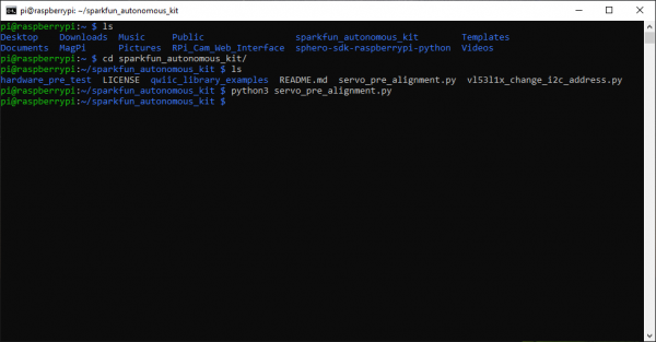
sparkfun_autonomous_kitdirectory is theservo_pre_alignment.pyexample code. Execute the example code.- Use the
lscommand list the files in the directory and to verify it is there. - To execute the example code, run
python3 servo_pre_alignment.py.
 Execute the
servo_pre_alignment.pyexample code. (Click to enlarge)- Use the
- The example code will align the pan (or horizontal movement) servo at 45° and the tilt (or vertical movement) servo at 37°. This position is ideal for the standard forward facing position. Channel 0 is configured for the pan servo and Channel 1 is configured for the tilt servo.

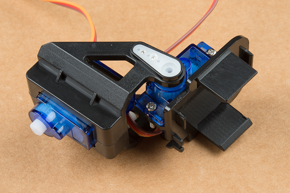 Standard forward facing or 90° postion.
(Click to enlarge)
 Standard forward facing position on chassis.
(Click to enlarge)
- Users should mark these positions with a marker. These marks should streamline the assembly process. Additionally, aligning the tilt servo at 37°, will hopefully prevent it from over-extending its position and thereby stripping out the gears when it is moved to 0° or 90°.
- Once completed, shutdown the Raspberry Pi using the
sudo shutdown nowcommand as mentioned in the Software Overview: Part 1 - Raspbian OS section. (*Remember... before unplugging the power or removing the SD card, be sure to verify that the Raspberry Pi has completely shutdown to avoid corrupting the SD card.)
Shutting down the Raspberry Pi. (Click to enlarge)
ACT LED indicating the end of the power down sequence, right before the power can be disconnected. (Click to enlarge)
Qwiic Devices
By now, users should have verified the functionality of the Raspberry Pi, the Pi Servo pHat, the servos, and the I2C bus. This section will verify the I2C functionality from the Pi Servo pHat with each Qwiic device, individually.
Qwiic Test
A simple test for users to check the connectivity of any attached I2C devices can be performed by pinging them with i2c-tools. In the command-line enter i2cdetect -y 1 and a readout of any detected devices will appear. For example, the servo controller IC should be at the 0x40 I2C address. (If the general call address is enabled, the 0x70 I2C address may appear as well.)
This is a table of the default I2C addresses for the hardware included in these kits.
| Hardware |
Pi Servo pHat (Not a Qwiic Device) |
Titan GPS Module | Qwiic Mux (TCA9548A) | VL53L1X ToF Sensor |
|---|---|---|---|---|
| Default I2C Address | 0x40 | 0x10 | 0x70 | 0x29 |
GPS (Titan X1) Module
For this test users will want to be in a location with their WiFi network coverage and a clear view of the sky. Access to an open window is a feasible option; however, it is not guaranteed to work. For example, on the bottom floor of a tall building, even if users stuck the GPS module out the window, it may still have issues getting a positional lock. If possible, a clearing or field, just outside a house or building, where there is still WiFi coverage is the ideal testing location.
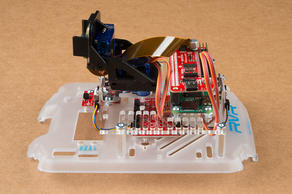
Users will need to assemble the Raspberry Pi Zero W with the Pi Servo pHat and attach the Titan (X1) GPS module using a Qwiic cable. To power the setup, users can use 4-pin UART cable and the Sphero RVR to make the test setup portable and carry it outside.
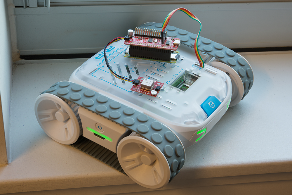
Once everything is assembled, power the Raspberry Pi by pressing the power button on the side of the Sphero RVR. Wait for the Raspberry Pi to finish booting and connecting to the WiFi network. Then, remotely access the Raspberry Pi using the SSH protocol from another computer and login.
Once logged in, users will want to run the GPS example code.
Change the current working directory to the
sparkfun_autonomous_kitfolder.- Users can use
cd sparkfun_autonomous_kitfrom thehomedirectory. - Otherwise, user can also
cd ~/sparkfun_autonomous_kitfrom any other location.
Change the directory to thesparkfun_autonomous_kitfolder. (Click to enlarge)- Users can use
Inside the
sparkfun_autonomous_kitdirectory is thehardware_pre_testfolder. Change the current working directory to thehardware_pre_testfolder.- Use the
lscommand list the files in the directory and to verify it is there. - Use the
cd hardware_pre_testcommand.
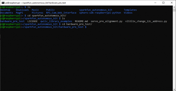 Change the directory to the
hardware_pre_testfolder. (Click to enlarge)- Use the
Inside the
hardware_pre_testdirectory is theTitanX1folder. Change the current working directory to theTitanX1folder.- Use the
lscommand list the files in the directory and to verify it is there. - Use the
cd TitanX1command.
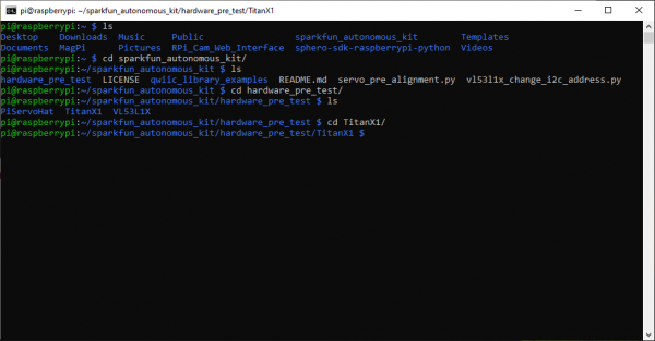 Change the directory to the
TitanX1folder. (Click to enlarge)- Use the
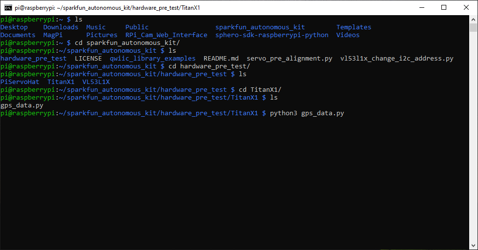
Inside the
TitanX1directory is thegps_data.pyexample code. Execute the example code.- Use the
lscommand list the files in the directory and to verify it is there. - To execute the example code, run
python3 gps_data.py.
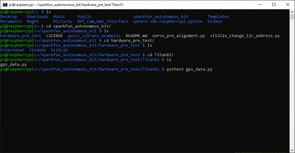 Execute the
gps_data.pyexample code. (Click to enlarge)- Use the
If it is working properly, users should see clear readout from the GPS module. It may take a minute or two for the GPS module to get an initial lock; the PPS LED is usually a good general indicator of a possible initial lock on the modules position. (The PPS LED is not necessarily an absolute indication that the module has a fix on its position.)
Additionally, the backup battery has enough energy for the GPS module to store pertinent data for a few days. Therefore, if the module has had a recent positional lock in the area, it may re-acquire its position a lot quicker.
Once users are finished testing, use Ctrl+C to terminate the script.


- That completes the GPS hardware test. Shutdown the Raspberry Pi using the
sudo shutdown nowcommand as mentioned in the Software Overview: Part 1 - Raspbian OS section. (*Remember... before unplugging the power or removing the SD card, be sure to verify that the Raspberry Pi has completely shutdown to avoid corrupting the SD card.)
Shutting down the Raspberry Pi. (Click to enlarge)
ACT LED indicating the end of the power down sequence, right before the power can be disconnected. (Click to enlarge)
Users who purchased the Basic kit should move on to the Hardware Assembly section. Otherwise, if you have the Advanced kit, continue below to finish testing the VL53L1X ToF sensors and the Qwiic Mux.
ToF (VL53L1X) Distance Sensors (Advanced Kit Only)
For this test users will want to be in an indoor location. Although the ToF sensor should be more than powerful enough to operate in daylight conditions, it would be advisable to test indoors to remove ambient light as a variable for the testing conditions. Users will need to assemble the Raspberry Pi Zero W with the Pi Servo pHat and attach one of the VL53L1X ToF distance sensors using a Qwiic cable.

Once everything is assembled, power the Raspberry Pi and wait for it to finish booting and connecting to the WiFi network. Then, remotely access the Raspberry Pi using the SSH protocol from another computer and login.
Once logged in, users will want to run the distance sensor example code.
Change the current working directory to the
sparkfun_autonomous_kitfolder.- Users can use
cd sparkfun_autonomous_kitfrom thehomedirectory. - Otherwise, user can also
cd ~/sparkfun_autonomous_kitfrom any other location.
Change the directory to thesparkfun_autonomous_kitfolder. (Click to enlarge)- Users can use
Inside the
sparkfun_autonomous_kitdirectory is theqwiic_library_examplesfolder. Change the current working directory to theqwiic_library_examplesfolder.- Use the
lscommand list the files in the directory and to verify it is there. - Use the
cd qwiic_library_examplescommand.
Change the directory to theqwiic_library_examplesfolder. (Click to enlarge)- Use the
Inside the
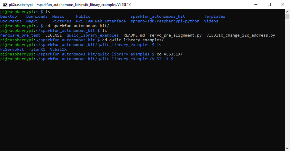
qwiic_library_examplesdirectory is theVL53L1Xfolder. Change the current working directory to theVL53L1Xfolder.- Use the
lscommand list the files in the directory and to verify it is there. - Use the
cd VL53L1Xcommand.
 Change the directory to the
VL53L1Xfolder. (Click to enlarge)- Use the
Inside the
VL53L1Xdirectory is theex1_read_distance.pyexample code. Execute the example code.- Use the
lscommand list the files in the directory and to verify it is there. - To execute the example code, run
python3 ex1_read_distance.py.
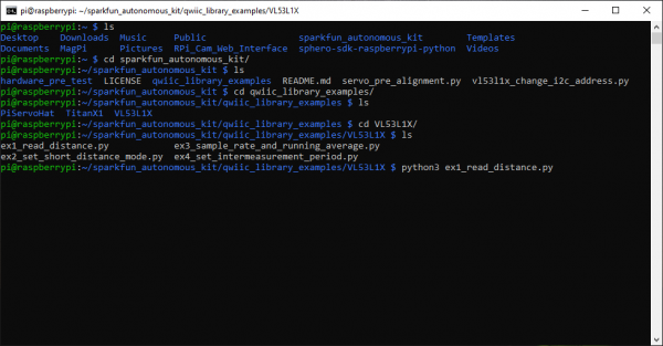 Execute the
ex1_read_distance.pyexample code. (Click to enlarge)- Use the
- If it is working properly, users should see clear readout from the VL53L1X ToF distance sensor. If users have a cellphone camera that does not have an IR filter, the camera can be used to detect the pulses of the IR laser. Once users are finished testing, use Ctrl+C to terminate the script.

 Running the distance sensor test code.
(Click to enlarge)
 Detecting pulses of IR laser. (Click to enlarge)
- Shutdown the Raspberry Pi using the
sudo shutdown nowcommand as mentioned in the Software Overview: Part 1 - Raspbian OS section. Then, swap the ToF sensors. (*Remember... before unplugging the power or removing the SD card, be sure to verify that the Raspberry Pi has completely shutdown to avoid corrupting the SD card.)- Users should shutdown and unplug the Raspberry Pi before swapping the sensors.
Shutting down the Raspberry Pi. (Click to enlarge)
ACT LED indicating the end of the power down sequence, right before the power can be disconnected. (Click to enlarge)
- Repeat the process to test the other ToF sensor.
- To jump directly to the
VL53L1Xdirectory:- Users can use
cd sparkfun_autonomous_kit/qwiic_library_examples/VL53L1Xfrom thehomedirectory. - Otherwise, user can also
cd ~/sparkfun_autonomous_kit/qwiic_library_examples/VL53L1Xfrom any other location.
- Users can use
- To jump directly to the
This completes the VL53L1X ToF distance sensor test, shutdown the Raspberry Pi using the sudo shutdown now command as done previously and move on to testing the Qwiic Mux below.
Qwiic Mux (Advanced Kit Only)
This is the last and final test! The VL53L1X ToF distance sensor has a "software" configurable I2C address; however it is "volatile", upon re-powering the device, it will automatically reset to the default I2C address. This is where the Qwiic Mux comes in. It is used to isolate the sensors, initially, so that the I2C address of one of the sensors can be reconfigured on power up. Again, since this test will use the VL53L1X sensors, users will want to be in an indoor location.
Users will need to assemble the Raspberry Pi Zero W with the Pi Servo pHat and attach the Qwiic Mux with a Qwiic cable. Then, on the Qwiic Mux, users should attach one of the VL53L1X ToF distance sensors to channels 0 or 4, using the Qwiic cables.

Once everything is assembled, power the Raspberry Pi and wait for it to finish booting and connecting to the WiFi network. Then, remotely access the Raspberry Pi using the SSH protocol from another computer and login.
Once logged in, users will want to run the VL53L1X address change example code.
Change the current working directory to the
sparkfun_autonomous_kitfolder.- Users can use
cd sparkfun_autonomous_kitfrom thehomedirectory. - Otherwise, users can also
cd ~/sparkfun_autonomous_kitfrom any other location.
Change the directory to thesparkfun_autonomous_kitfolder. (Click to enlarge)- Users can use
Inside the
sparkfun_autonomous_kitdirectory is thevl53l1x_change_i2c_address.pyexample code. Execute the example code.- Use the
lscommand list the files in the directory and to verify it is there. - To execute the example code, run
python3 vl53l1x_change_i2c_address.py.
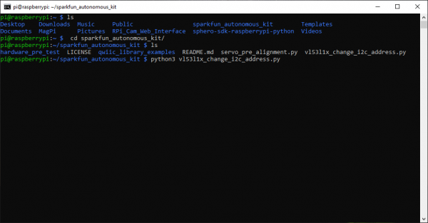 Execute the
vl53l1x_change_i2c_address.pyexample code. (Click to enlarge)- Use the
Follow the prompts of the example code. When selecting which channel on the Mux to enable, select the channel that the VL53L1X ToF distance sensor is attached to (i.e. channels 0 or 4, from the instructions earilier). If users have successfully performed the I2C address change, they should be able to test the sensor on the new I2C address. Once users are finished testing, use Ctrl+C to terminate the script.
 Running the I2C address change code. (Click to enlarge)

- After the the test is complete, shutdown the Raspberry Pi using the
sudo shutdown nowcommand as mentioned in the Software Overview: Part 1 - Raspbian OS section. (*Remember... before unplugging the power or removing the SD card, be sure to verify that the Raspberry Pi has completely shutdown to avoid corrupting the SD card.)- Users should shutdown and unplug the Raspberry Pi before swapping the sensors.
Shutting down the Raspberry Pi. (Click to enlarge)
ACT LED indicating the end of the power down sequence, right before the power can be disconnected. (Click to enlarge)
This completes all the hardware pre-test; please, move on to the Hardware Assembly section below.