Getting Started with the LilyPad MP3 Player
 MikeGrusin
Getting to Know the LilyPad MP3 Player
The LilyPad MP3 Player comes with preinstalled software called "Trigger" that will play specific files when the input pins are grounded. You can also add an optional rotary encoder and load the "Player" software to turn the board into a "real" audio player, or even write your own software using the free Arduino programming environment.
Anatomy of the LilyPad MP3 Player:
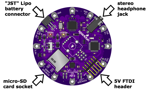
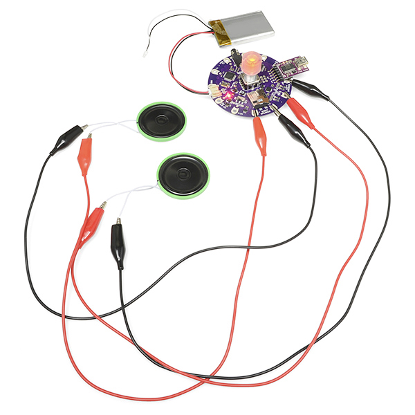
Let's start with the connectors. You will normally power the board with a single-cell (3.7V) Lipo battery, which plugs into the two-pin "JST" battery connector. There is a stereo headphone jack that you can use to connect the board to a pair of headphones if desired. Connecting headphones will disable the speakers, but you can change this behavior if you wish. (If you'd like to connect the board to an external amplifier, see the special note here.) You can plug a 5V FTDI board or cable into the 6-pin 5V FTDI header, to both recharge an attached Lipo battery and to reprogram the board if desired (see this note about powering the board from USB). And finally, there is a micro-SD card socket into which you'll insert a micro-SD memory card containing the audio files you want to play.
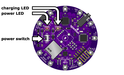
The board contains a power switch that is used to turn the board on and off. There are also two LEDs; a red power LED that will light up when the board is powered on, and a yellow charge LED. The charge LED will light up when the battery is being charged, and go out when it is full. (It is also normal for the charge LED to turn on if no battery is attached.) You can charge the battery while the board is on or off, but the battery will charge faster if the board is off.
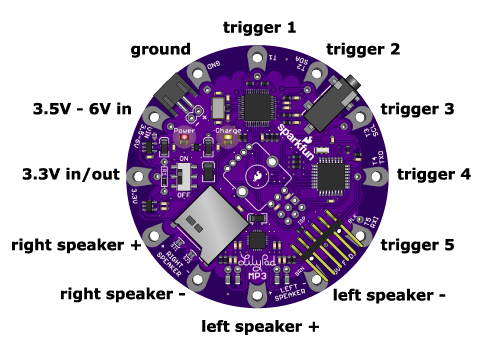
The LilyPad MP3 Player has twelve "pins" (they're really holes, but they connect to pins on the microcontroller) that you'll use to connect to the outside world. For each pin, we've provided both "sew taps" (large holes you can loop conductive thread around to use it in fabric projects), and standard headers (smaller holes that you can solder wires or header pins to if you wish).
Five of the pins are set up to be triggers, which you can use with the default software to trigger playback of specific audio files. (We'll learn more about this on the next page, "Using the default trigger sketch".) Typically you'll connect triggers to switches that activate the playback of various audio files. Many of the triggers also have alternate functions, such as serial ports, that you can use to communicate with other devices in more complex projects. The alternate functions are listed in the table below.
You'll also use the pins to connect to external speakers. The LilyPad MP3 Player includes a stereo (two channel, left and right) amplifier that supports speakers between 4 and 8 ohms. Each speaker has two terminals, labeled "+" and "-". Normally you'll connect two speakers to the board, but you can also use just one speaker if you wish, or connect multiple speakers in series or parallel. Just don't connect the speaker pins to anything but a speaker or transducer.
Here is a table of the pins and their functions:
| pin name | function | notes |
| VIN | Raw voltage in (3.5V to 6V) | If you don't want to connect a Lipo battery, you can use this pin to power the board from an external supply. If you want to also charge an attached Lipo battery, this input should be between 4.5V and 6V. You can read more about your options for powering the board here. |
| 3.3V | Regulated 3.3V in or out | If you already have a regulated 3.3V supply, you can use this pin to power the board. (Powering the board through this pin will not charge the battery.) You can also pull 3.3V power out of this pin if you need it somewhere else. |
| GND | Ground (0V) | Use as a power ground, and also for the return side of your trigger switches (see the diagram here). |
| T1 | Trigger 1 | General purpose I/O pin (Arduino pin A0). You'll usually connect this through a switch to ground. Can also be used as an analog input. |
| T2 | Trigger 2 / SDA | General purpose I/O pin (Arduino pin A4). You'll usually connect this through a switch to ground. Can also be used as SDA (serial data) in an I2C ("wire" library) connection (4.7K pullup included), or an analog input if the pullup is disabled. |
| T3 | Trigger 3 / SCL | General purpose I/O pin (Arduino pin A5). You'll usually connect this through a switch to ground. Can also be used as SCL (serial clock) in an I2C ("wire" library) connection (4.7K pullup included), or an analog input if the pullup is disabled. |
| T4 | Trigger 4 / TX | General purpose I/O pin (Arduino pin D1). You'll usually connect this through a switch to ground. Can also be used as TX (transmit) in a serial connection. Do not permanently pull this pin low or reprogramming and serial monitoring will be disabled. |
| T5 | Trigger 5 / RX | General purpose I/O pin (Arduino pin D0). You'll usually connect this through a switch to ground. Can also be used as RX (receive) in a serial connection. Do not permanently pull this pin low or reprogramming and serial monitoring will be disabled. |
| Right Speaker + | Right Speaker + | Connect to the right speaker + terminal. Only connect to a speaker or other coil-based transducer. Do not short to power, ground, or any other signal. |
| Right Speaker - | Right Speaker - | Connect to the right speaker - terminal. Only connect to a speaker or other coil-based transducer. Do not short to power, ground, or any other signal. |
| Left Speaker + | Left Speaker + | Connect to the left speaker + terminal. Only connect to a speaker or other coil-based transducer. Do not short to power, ground, or any other signal. |
| Left Speaker - | Left Speaker - | Connect to the left speaker - terminal. Only connect to a speaker or other coil-based transducer. Do not short to power, ground, or any other signal. |
You may have noticed the unused footprint in the middle of the board. That is there to allow you to add an optional RGB rotary encoder if you wish. You won't need it to run the preinstalled "Trigger" software, but if you want to turn the LilyPad MP3 Player into a true audio player, the rotary encoder provides a simple user interface to switch tracks and change the volume. See the "Getting started with the player sketch" page for more information.
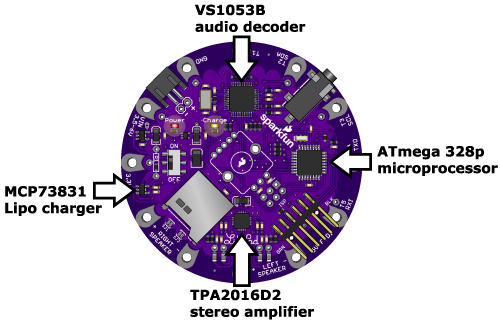
In case you're interested in the hardware on the board, there is an ATmega 328p microprocessor, running Arduino software that pulls data from audio files on the micro-SD card and feeds that data to the VS1053B audio-decoding chip. The VS1053B transforms the digital audio data back into analog audio signals. The audio signals are sent to the headphone jack and a TPA2016D2 stereo amplifier, which boosts the audio signal for the speakers. We also threw in a MCP73831 Lipo battery charger to make it easy to recharge the battery from the FTDI port. Neat, huh?
Tips on speaker selection
The TPA2016D2 stereo amplifier on the LilyPad MP3 Player is capable of driving about a watt of power into each channel. This doesn't sound like much, but it can produce surprising volume from a large speaker.
In general, larger speakers will sound better than small ones, so use the largest ones that your project will accommodate. Don't worry that the speaker is marked "20 watts" or higher; that is just the maximum power that the speaker is designed to handle. We've had great results with recycled automotive and PC speakers, and even large cabinet speakers.
If your project requires a small speaker, remember that any small speaker will sound much better if it has an enclosed cavity behind it. You can do this with a project enclosure, recycled food containers, etc. Use your imagination!
Some important things to know:
Always turn the LilyPad MP3 Player off before inserting or removing the micro-SD card. This will prevent corruption of the data on the card.
The 5V FTDI port is provided to charge an attached Lipo battery, and provide a way to reprogram the board. It will power the board if no audio is playing, but will not provide enough power to drive the speakers (the board will reset while playing). In general, the best way to power the LilyPad MP3 Player is with a Lipo battery. If you'd like to use an external supply, see the instructions here, and if you really want to run the board from FTDI power you can hack it to do so.
To recharge an attached Lipo battery, plug a 5V FTDI Basic or cable into the 6-pin FTDI connector. Match up the direction of your FTDI board or cable with the "GRN" and "BLK" markings on either side of the connector. The yellow "Charge" light will turn on while the battery is charging and turn off when it's fully charged. It's normal for the charge light to turn on if no battery is attached. The charge rate is set to 500mA, which means that a 1000mAh battery will charge in about two hours. If you'd like to change the charge rate, see the instructions here.
The LilyPad MP3 Player's headphone jack is safe for headphones, but don't connect it to an external amplifier unless you're using a battery to power the LilyPad. (The fine print is that if the audio ground is shorted to the power ground, the audio decoder chip will be damaged).
The VS1053B chip understands a large variety of audio file formats, but we'll occasionally run into one it can't play back (it will quietly skip it). See the list of formats and bitrates it understands here. If you do run into a file it has problems with, you can often fix the problem by translating the file into a different format using the audio software of your choice.
The LilyPad MP3 Player is washable, but because conductive thread connections can be fragile, we recommend washing your project as little as possible. Please hand-wash, and be sure to remove the Lipo battery and micro-SD card before washing. Because water can get into lots of little crevices, allow everything to air-dry for several days before powering it up again.
With that out of the way, let's start playing audio!