Getting Started with the MyoWare® 2.0 Muscle Sensor Ecosystem
 QCPete
 bboyho
MyoWare 2.0 Power Shield
 |
 |
| v 2.0.3 | v 2.0.2 |
The MyoWare 2.0 Power Shield is designed to easily power the MyoWare 2.0 Muscle Sensor for remote applications. The MyoWare Power Shield is equipped with snap connectors on the board so you can easily stack it to the top side of the MyoWare Muscle Sensor. Flip the switch to the ON position to give the sensor all the power it needs to work its myoelectric magic. Connecting the MyoWare 2.0 Muscle Sensor to battery power allows for a cleaner signal while also eliminating the possibility of creating a dangerous current path to the power grid. Use it to power your sensor in portable applications.
Hardware Overview
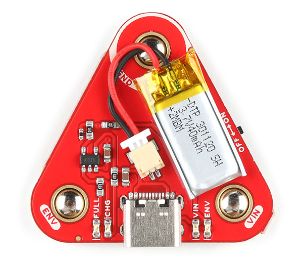
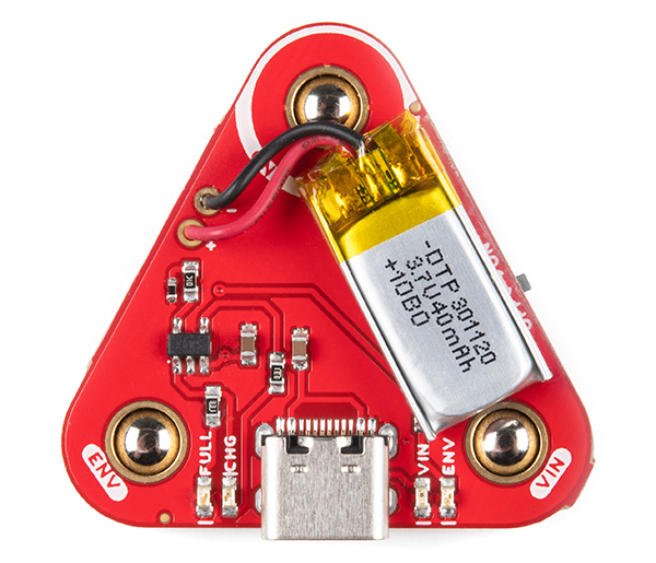
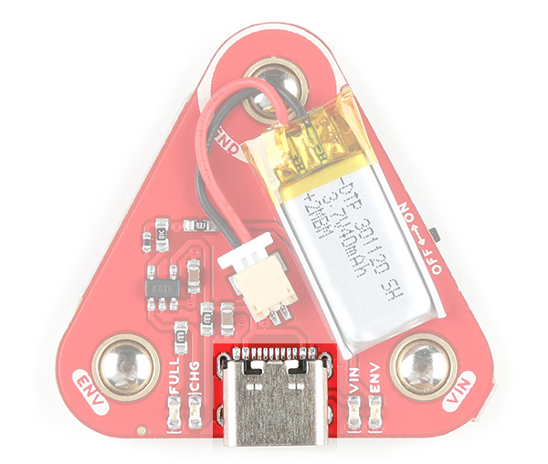
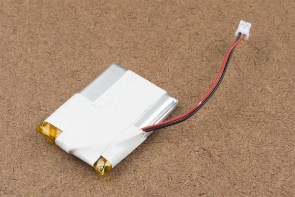
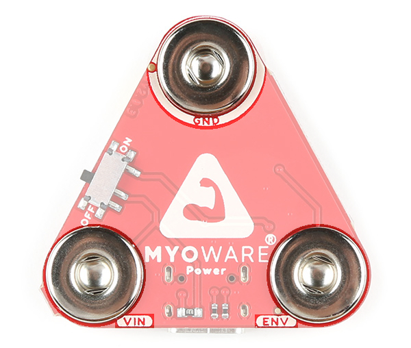
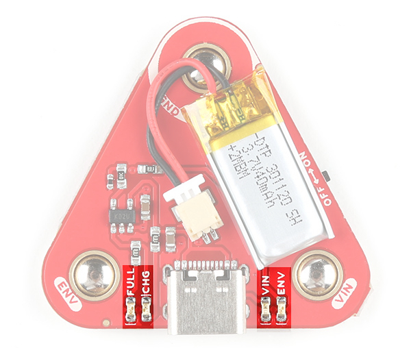
The top side of the board has the LiPo battery and the USB connector. The bottom side has the female snap connectors and a power switch.
|
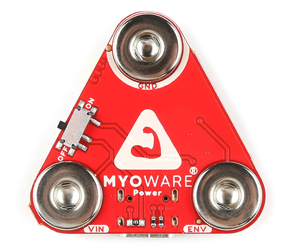 |
| Top Side | Bottom Side |
USB C Connector
Included on the board is a USB Type C connector. Plug in a USB C cable to a 5V power source to charge the single cell LiPo battery.
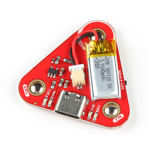
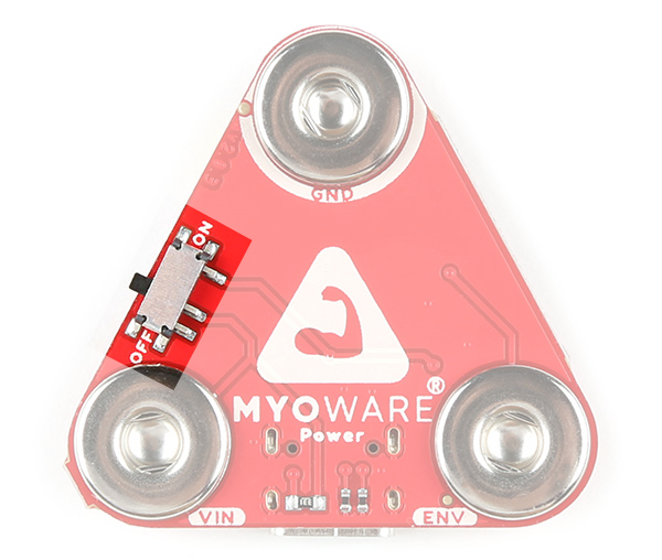
Power Switch
The board includes a power switch. Flip the switch to the ON position to provide power to the MyoWare 2.0 Muscle Sensor via the VIN female snap connector. When not in use, flip the switch to the OFF position.
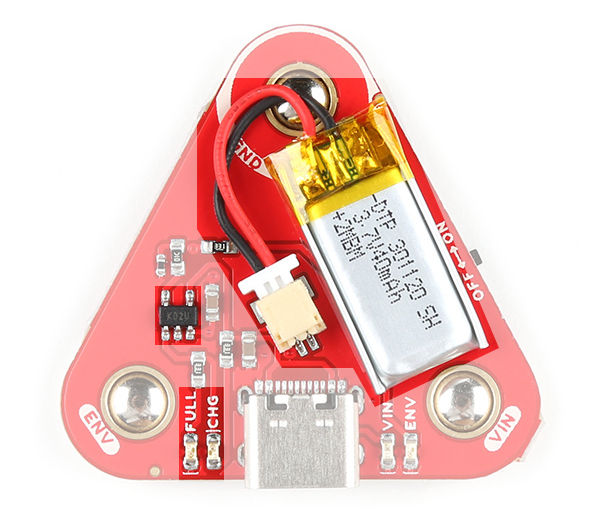
LiPo Charger
The board includes the MCP73831 LiPo charger IC (the little black IC with 5 pins) to safely charge a single cell LiPo battery. In this case, the charge rate is set to 40mA to charge the built-in 40mAh LiPo battery. The charge status of your battery is indicated by the charge (CHG) and full (FULL) LEDs.
Snap Connectors
The board includes three female snap connectors to easily stack on top of the MyoWare 2.0 Muscle Sensor:
- GND - Ground for power.
- VIN - Voltage input for power. This voltage depends on how much the LiPo battery is charged up. When plugged in to a power source for charging, the charge IC may start charging the LiPo battery and will be about 4.2V. For safety reasons, we recommend that users always disconnect this shield from the sensor when charging the battery.
- ENV - Envelope signal ranging between 0-VIN. Connect this to an ADC on your microcontroller.
LEDs
The board includes four LEDs on the top side of the board:
- FULL - The FULL LED lights up to indicate when the battery is fully charged. This will be off when the LiPo is not charging or when the charger is not connected to the board.
- CHG - The CHG LED lights up to indicate when the LiPo battery is charging. This will be off when the LiPo is fully charged or when the charger is not connected to the board.
- VIN - The VIN LED lights up when the power switch is flipped to the ON position to indicate when the board is providing power for the MyoWare 2.0 Muscle Sensor through the VIN snap pin.
- ENV - The ENV pin lights up when there is activity from the MyoWare 2.0 Muscle Sensor's ENV pin.
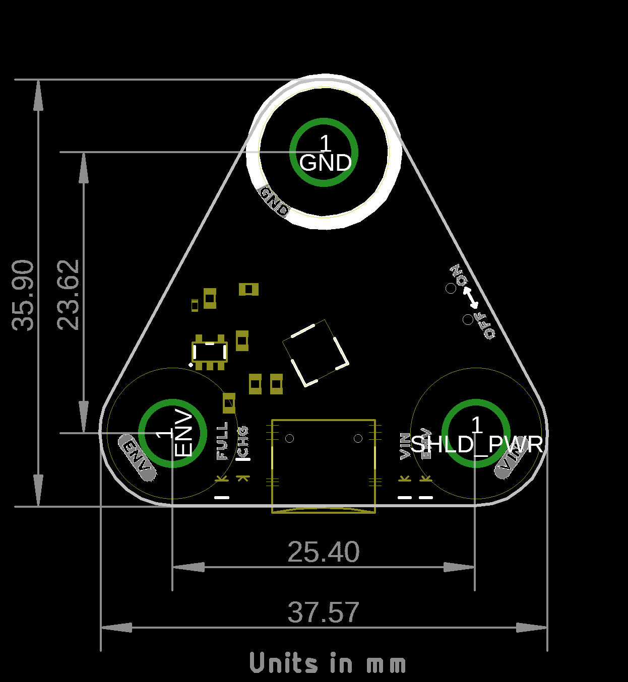
Board Dimensions
The shield uses the MyoWare 2.0 Muscle Sensor form factor and has board dimensions of 37.57mm x 35.90mm (1.48” x 1.41”).