Getting Started with the MyoWare® 2.0 Muscle Sensor Ecosystem
 QCPete
 bboyho
Arduino Example 1: Analog Read - Single Sensor
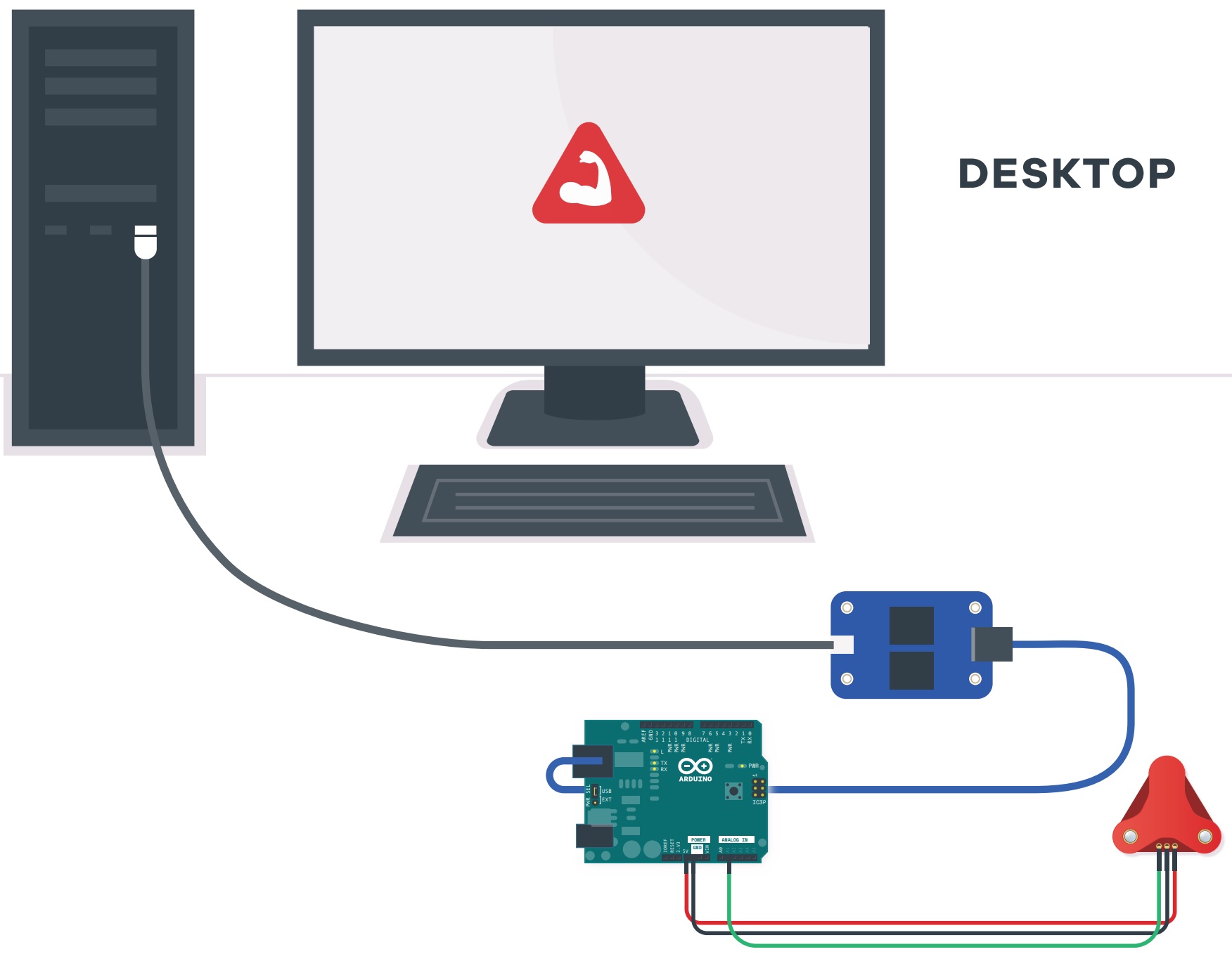
Image Courtesy of Advancer Technologies taken from the MyoWare 2.0 Quick Start Guide
If you do not have a USB isolator, try using a laptop running on battery power and ensure that you are not connecting the laptop to a wall outlet.

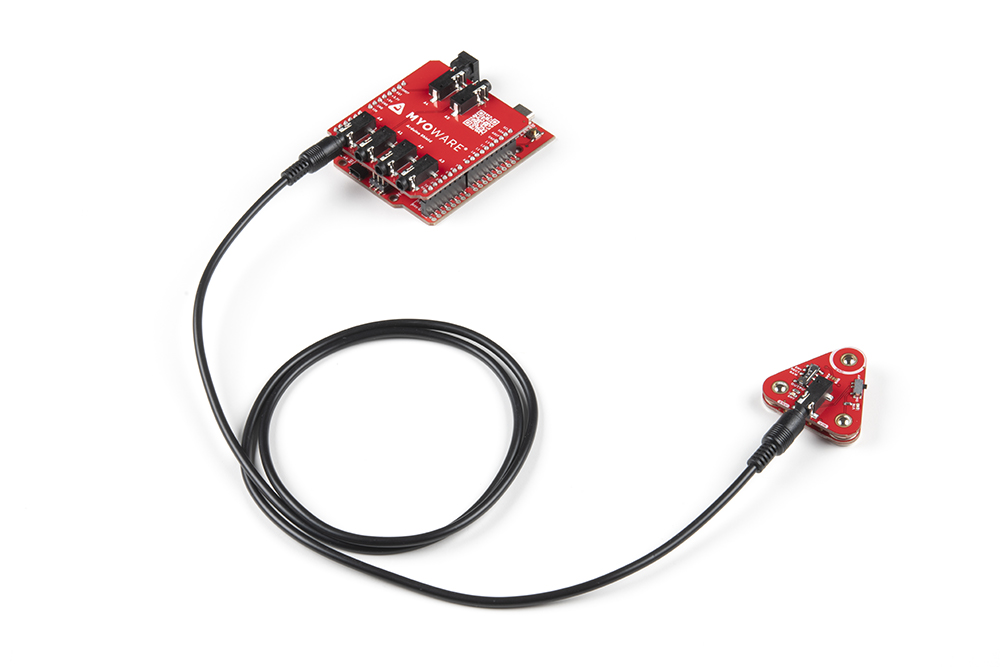
Image Courtesy of Advancer Technologies taken from the MyoWare 2.0 Quick Start Guide
We also recommend using a wireless keyboard and mouse when programming in Arduino. The muscle sensor is sensitive enough that it can also pick up a signal from the trackpad or keyboard on your laptop when running on power. As a result, the muscle sensor will have false readings and the Arduino's analog pin will read high.
Example 1: Analog Read - Single
The following example uses an analog input on the RedBoard Plus with an Atmega328P to read the muscle sensor's analog signal. However, you could also use any microcontroller with the Arduino Uno R3 footprint.
If you have not already, select your Board (in this case the Arduino Uno), and associated COM port. Upload the code to the board.
language:c
/*
  MyoWare Example_01_analogRead_SINGLE
  SparkFun Electronics
  Pete Lewis
  3/24/2022
  License: This code is public domain but you buy me a beverage if you use this and we meet someday.
  This code was adapted from the MyoWare analogReadValue.ino example found here:
  https://github.com/AdvancerTechnologies/MyoWare_MuscleSensor

  This example streams the data from a single MyoWare sensor attached to ADC A0.
  Graphical representation is available using Serial Plotter (Tools > Serial Plotter menu).

  *Only run on a laptop using its battery. Do not plug in laptop charger/dock/monitor.

  *Do not touch your laptop trackpad or keyboard while the MyoWare sensor is powered.

  Hardware:
  SparkFun RedBoard Artemis (or Arduino of choice)
  USB from Artemis to Computer.
  Output from sensor connected to your Arduino pin A0

  This example code is in the public domain.
*/

void setup()
{
  Serial.begin(115200);
  while (!Serial); // optionally wait for serial terminal to open
  Serial.println("MyoWare Example_01_analogRead_SINGLE");
}

void loop()
{
  int sensorValue = analogRead(A0); // read the input on analog pin A0

  Serial.println(sensorValue); // print out the value you read

  delay(50); // to avoid overloading the serial terminal
}
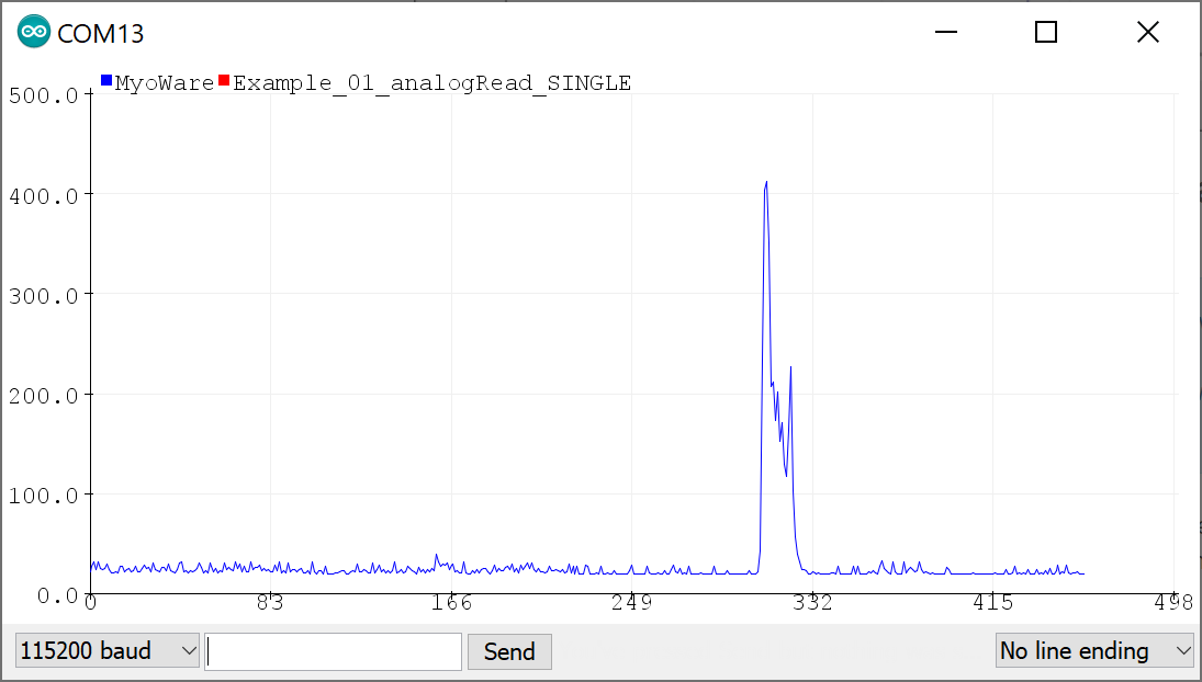
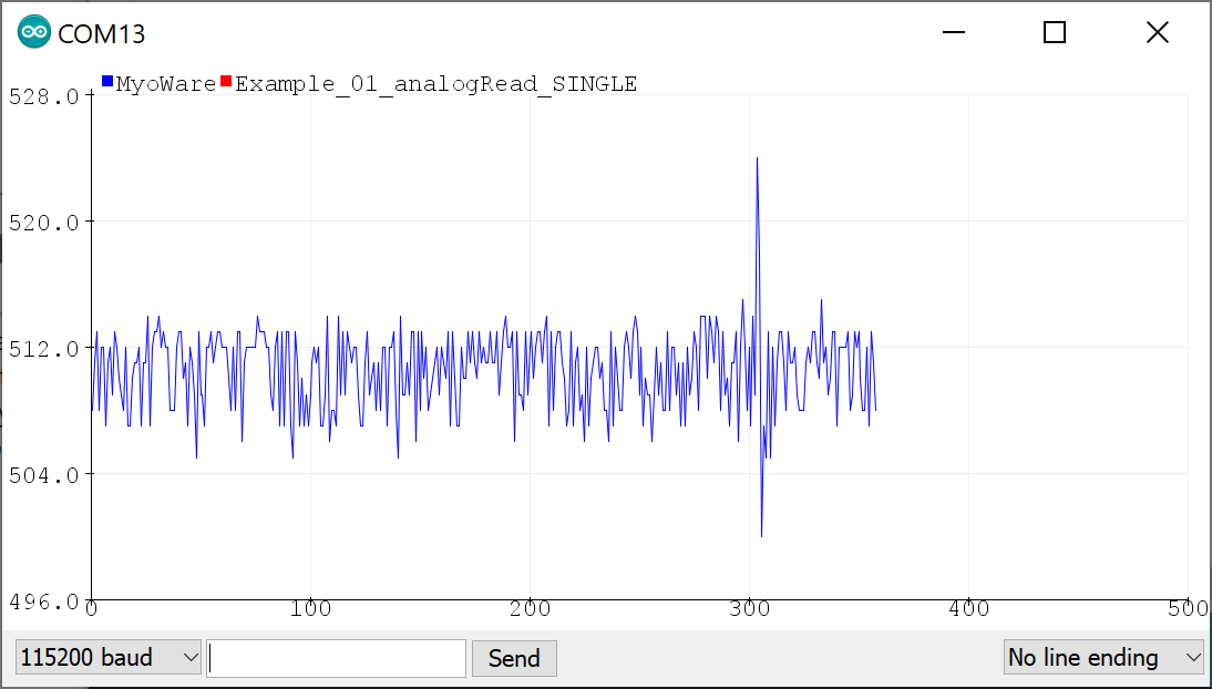
Once uploaded, open the Arduino Serial Plotter (Tools > Serial Plotter) to 115200 baud. Flip the power switch on the MyoWare 2.0 Link Shield to provide power and start flexing! You should see something similar to the output below with the envelope signal. In this case, the MyoWare 2.0 Muscle Sensor was attached to my right forearm. For those that are interested in viewing the serial output, you can also open the Arduino Serial Monitor to see the values.
To view the Rectified or Raw signals, flip the power switch to the OFF position on the Link Shield, adjust the OUTPUT switch to either the Rectified or Raw position and then turn the power switch to the ON position. Reopen the Serial Plotter and you will see a smaller signal output when flexing your forearm.
The images below show the forearm being flexed at around 300ms when the signal increases by a value of about 22 for the rectified output and about 20 for the raw output. Note that the raw signal will be centered around a voltage offset of about +VIN/2. Make sure that the +VIN is the maximum voltage of your microcontroller's ADC to ensure that you can see the positive and negative portions of the waveform. The output shown in the graphs are values and have not been converted to voltages.
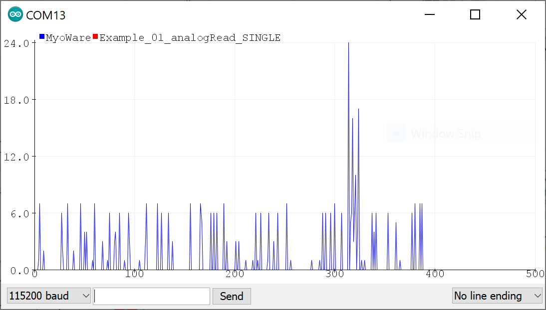 |
 |
| Serial Plotter with Rectified Signal | Serial Plotter with Raw Signal |