Getting Started with the MyoWare® 2.0 Muscle Sensor Ecosystem
 QCPete
 bboyho
MyoWare 2.0 Muscle Sensor
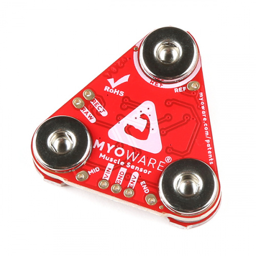
The MyoWare 2.0 Muscle Sensor is an Arduino-compatible, all-in-one electromyography (EMG) sensor from Advancer Technologies! The innovative snap connector system eliminates the need to solder connections for the MyoWare 2.0 ecosystem. It's that easy: stick on a few electrodes (not included), read the output voltage and flex some muscles! The muscle sensor’s snap connector system makes it easier to stack shields together. The top side connectors link to power and the sensor’s EMG envelope output while the bottom side links to the input electrodes. Measuring muscle activity by detecting its electric potential has traditionally been used for medical research. However, with the advent of ever shrinking yet more powerful microcontrollers and integrated circuits, EMG circuits and sensors have found their way into all kinds of control systems such as video games, robotics, and prosthetics!
The embedded snap connectors mate well with our biomedical sensor pad (10 pack).
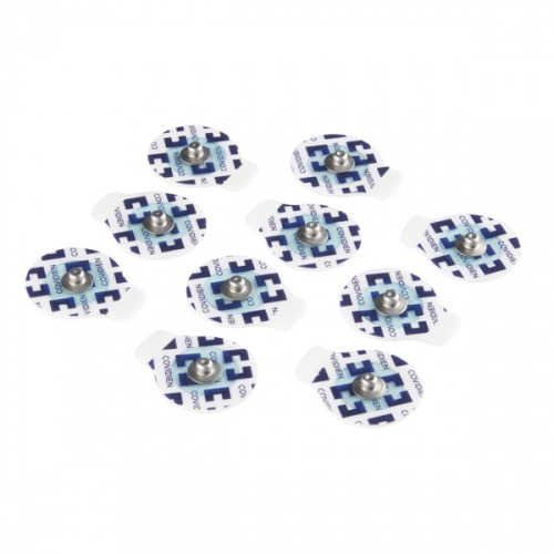
Hardware Overview
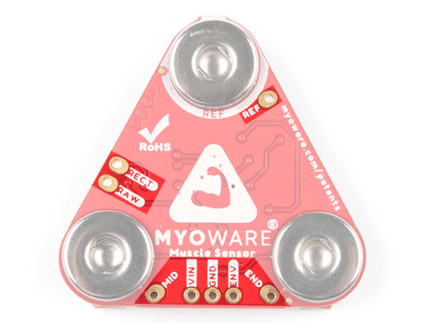
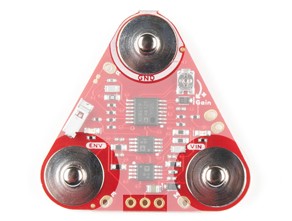
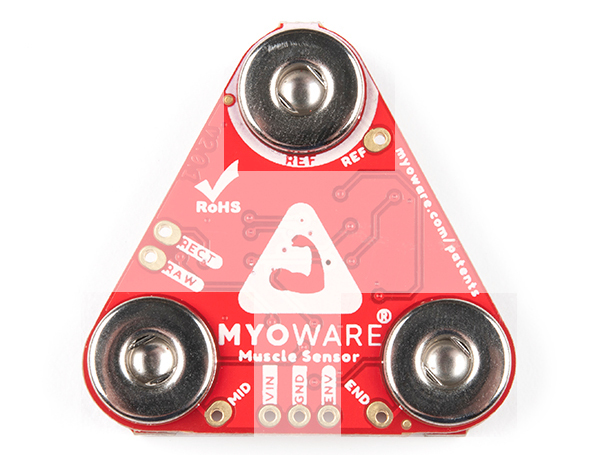
The top side of the board is populated with the circuit and male snap connectors. The bottom of the board has the female snap connectors.
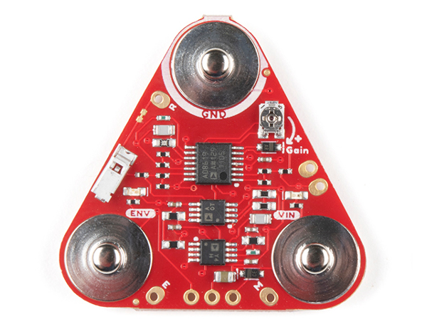 |
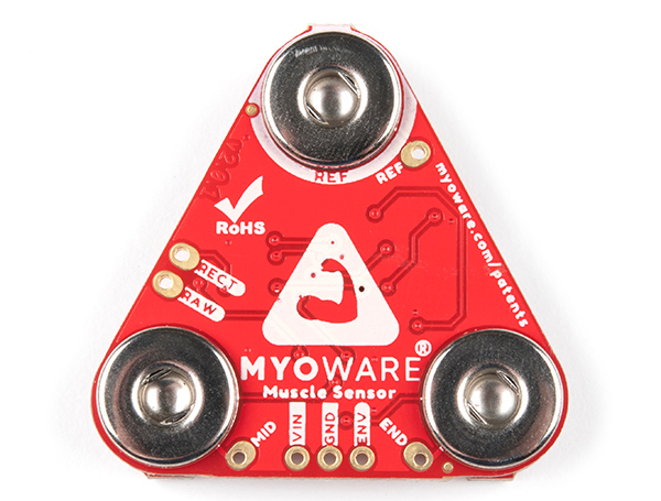 |
| Top Side | Bottom Side |
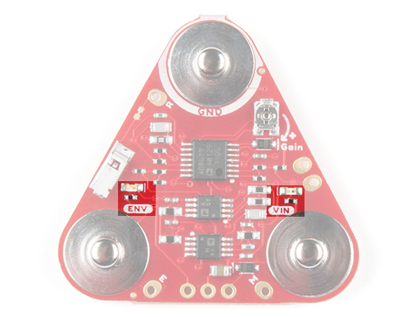
Amplifiers and Adjustable Gain
The MyoWare 2.0 Muscle Sensor measures a small EMG reading from the muscle group. This signal goes through an amplifier, bandpass filter, rectifier, and envelope detector so that users can easily read the muscle activity through a microcontroller's ADC pin.

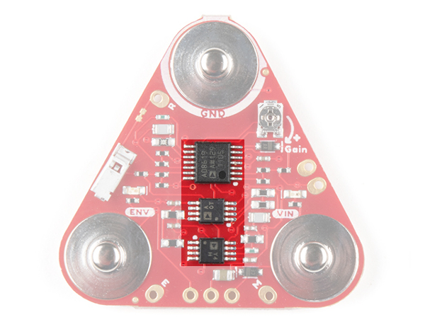
The ICs highlighted below are amplifiers used to help process the raw EMG signal. As stated from the MyoWare 2.0 Advanced Guide, some of the muscle sensor's technical specifications are as follows:
- Voltage Input
- min. = +2.27V
- typ. = +3.3V or +5V
- max. = +5.47V
- Input Bias Current
- 250 pA, max 1 nA
- Input Impedance
- 800
- Common Mode Rejection Ratio (CMRR)
- 140dB
- Filters
- High-pass Filter: Active 1st order, fc = 20.8 Hz, -20dB
- Low-pass Filter: Active 1st order, fc = 498.4 Hz, -20dB
- Rectification Method
- Full-wave
- Envelope Detection
- Linear: Passive 1st order, fc = 3.6 Hz, -20 dB
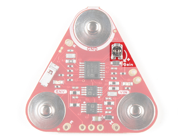
The board includes a potentiometer (trim pot) to manually adjust the gain of the envelope signal. You will need a screwdriver to adjust. Of course the top shield will need to be disconnected to access the potentiometer. The gain (G) for the following signals are as follows:
- Raw (RAW): G = 200
- Rectified (RECT): G = 200
- Envelope (ENV): G = 200 * (R / 1 kΩ), where R is the resistance of the gain potentiometer in kΩ
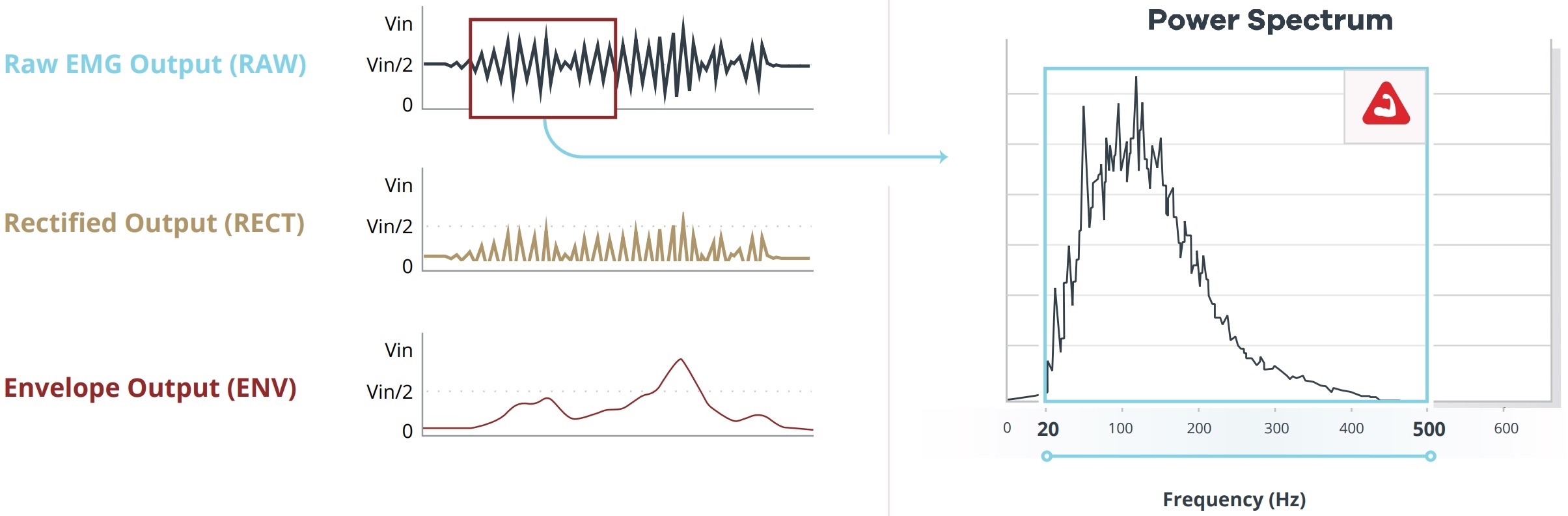
The image below shows the waveforms for the raw, rectified, and envelope outputs. The graph to the right of the outputs show the raw output's power spectrum. The MyoWare 2.0 Muscle Sensor has a first-order bandpass filter ranging between 20Hz - 500Hz. This range is ideal for capturing the the raw EMG signal and removing any unwanted signals such as motion artifacts. Note that the data shown is for illustration purposes only and not the actual data.
PTH Pads
Flipping the board to the bottom side, you will see PTH pads labeled. For those that need to solder wire to connect VIN, GND, and ENV, we have included a 1x3 row of 0.1" spaced PTH pads on the board. Additionally, the RAW, RECT, REF, MID, and END pins are broken out throughout the board. When soldering wire to the REF, RECT, and RAW pins, care must be taken to avoid adding excessive solder to the pins as this may prevent the MyoWare 2.0 Link Shield's pogo pins from connecting properly to the PTH pads.
LEDs
The board includes two status LEDs.
- VIN - The VIN LED lights up when the power switch is flipped to the ON position to indicate when the board is providing power for the MyoWare 2.0 Muscle Sensor through the VIN snap pin.
- ENV - The ENV pin lights up when there is activity from the MyoWare 2.0 Muscle Sensor's ENV pin.
Snap Connectors
The board includes snap connectors to easily stack shields on the MyoWare 2.0 Muscle Sensor. The top of the board is slightly offset and designed to act like a key so there's only one way to connect the boards together. Align the GND or REF snap connectors before stacking the boards together. Otherwise, the three snap connectors will fail to connect.
The following male snap connectors are on the top side of the board. These are also broken out on the 1x3 header on the bottom of the board. Flip the board over to view the pin labels.
- GND - Ground for the MyoWare 2.0 Muscle Sensor.
- VIN - Voltage input for the MyoWare 2.0 Muscle Sensor. This voltage depends on what shield is stacked on top when using the snap connectors. Make sure to leave the VIN pin's PTH pad open when stacking a shield on top to avoid conflicting voltages from two power sources.
- When using it with the MyoWare 2.0 Power Shield or LED Shield, it will depend on how much the LiPo battery is charged up. When plugged in to a power source for charging, the charge IC may start charging the LiPo battery and system voltage will be about 4.2V. For safety reasons, we recommend that users always disconnect this shield from the sensor when charging the battery.
- When using it with the MyoWare 2.0 Link Shield and MyoWare 2.0 Arduino Shield, it depends on the position of the Power Jumper on the MyoWare 2.0 Arduino Shield. This sets VIN to 5V (default) or 3.3V.
- ENV - Envelope signal ranging between 0-VIN. Connect this to an ADC on your microcontroller.
The following female snap connectors are on the bottom side of the board. These are broken out onto a PTH pad next to each snap connector.
- REF - Reference electrode snap connector. Connect this to a separate section of the body such as a bony portion of the elbow or a nonadjacent muscle near the muscle group.
- MID - Middle muscle electrode snap connector. Connect to the middle of the muscle group.
- END - End muscle electrode snap connector. Connect to the end of the muscle group.
Reference Electrode Port
The board has a housing to insert the reference cable's crimped pin. By inserting the pin to its housing and placing a biomedical sensor pad into the electrode snap, you can stick the reference cable to a separate section of the body such as a bony portion of the elbow or a nonadjacent muscle near the targeted muscle where the built-in reference pin is unable to reach.
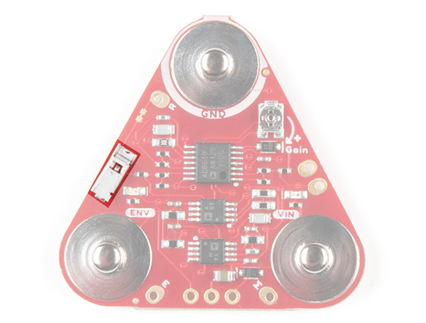
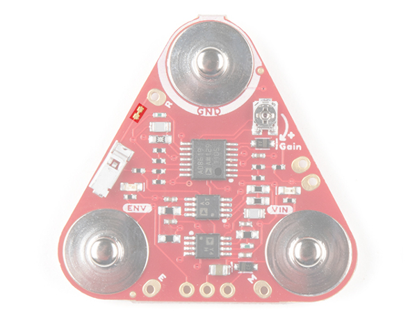
Jumper
There is a small jumper beside the reference pin labeled "R". This jumper is closed by default and connects to the reference electrode connector. Make sure to cut this trace when using the reference cable. For more information on modifying the jumpers, check out our tutorial on working with jumper pads and PCB traces.
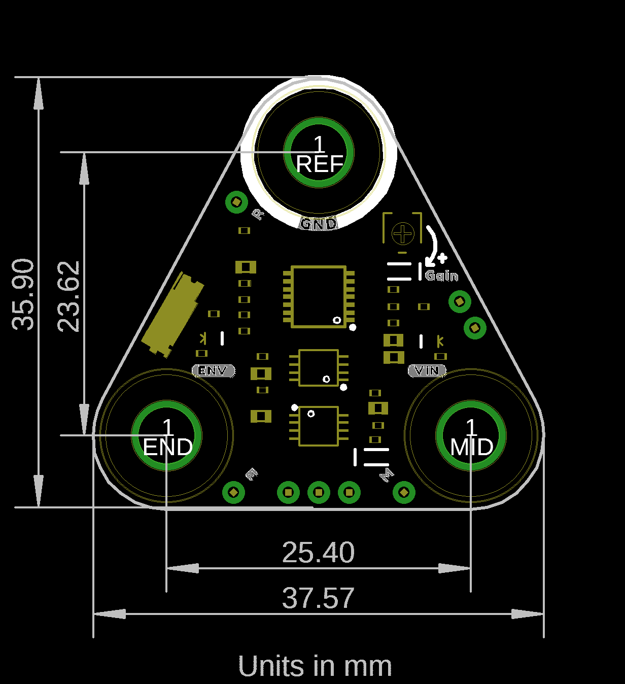
Board Dimensions
The MyoWare 2.0 Muscle Sensor board dimension is 37.57mm x 35.90mm (1.48” x 1.41”).