Getting Started with the Red Hat Co.Lab Robot
 D___Run___,
  Gina Likins
Build: Assemble line sensors
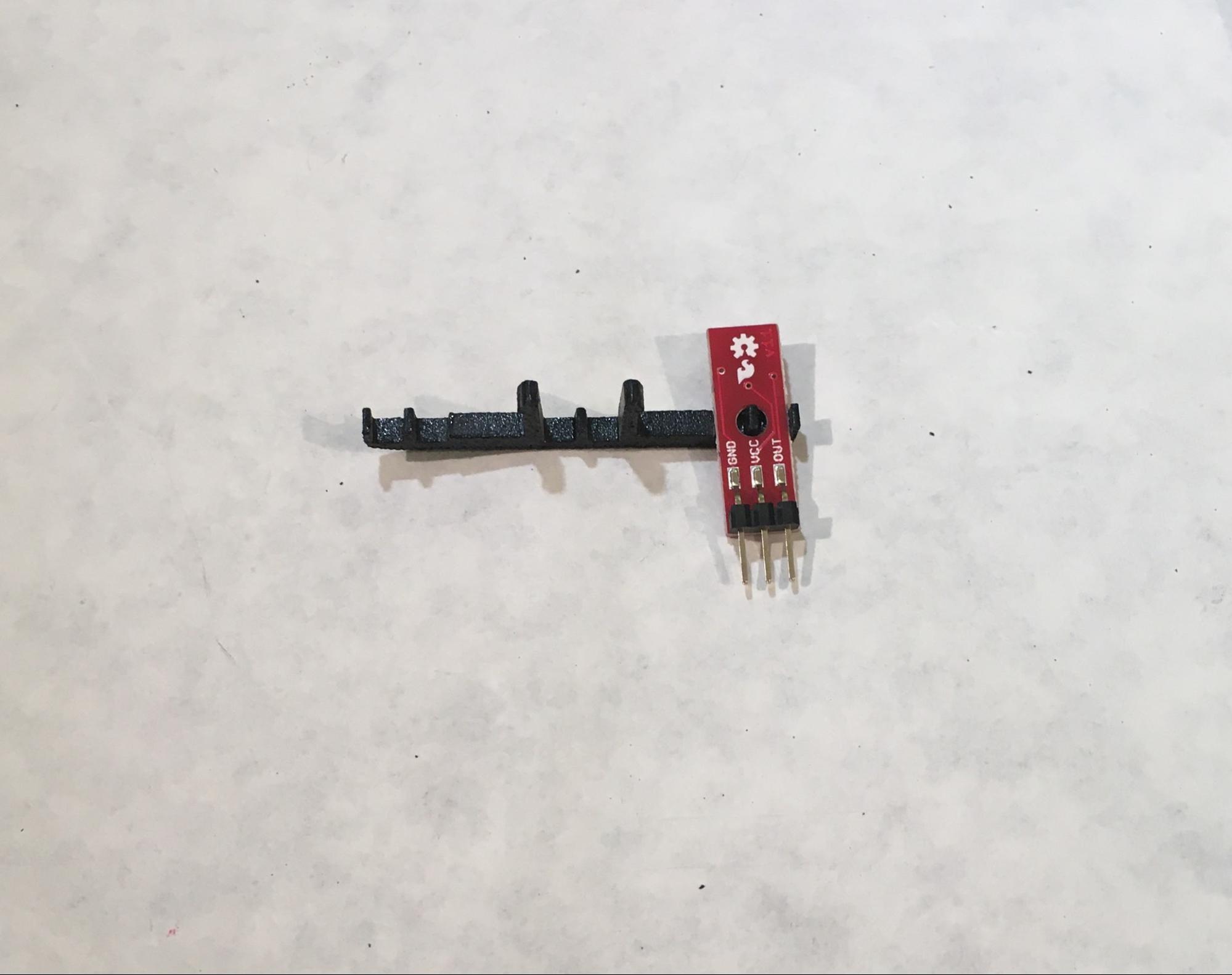
The Line Sensors (which we’re installing now, but will use in the next tutorial) emit light from an infrared LED and then detect that light once it has been reflected off an object. This allows your robot to “see” lines!
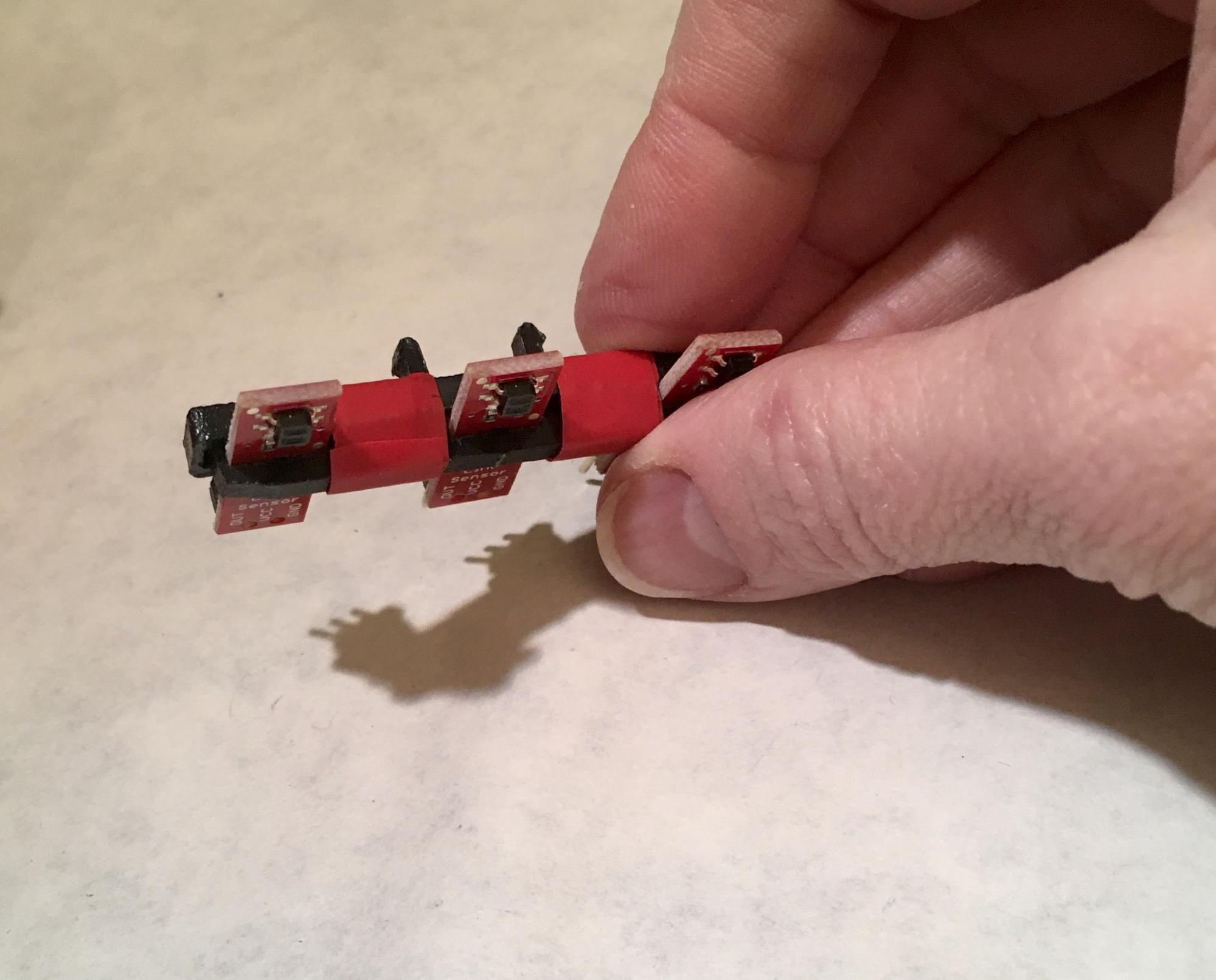
Take one of your three Line Sensors and turn it so the sensor faces down and the side with pins faces up. Attach it to the Line Follower Mount by putting the hole in the Line Sensor over the small peg on the Line Follower Mount, like this:
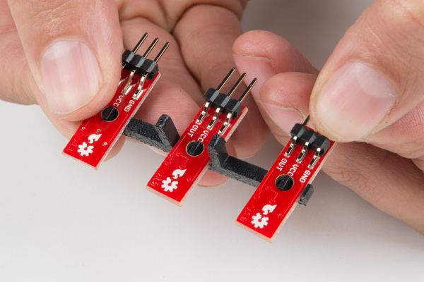
Repeat for the next two sensors, so that when all three are set on the Line Follower Mount, you have something that looks like this (notice that the sensors are facing away/down from the prongs of the mount):
Place the Line Follower Mount Plate on top of the Line Follower Mount, sandwiching the Line Sensors in between the two. The center clip of the mount should poke through the center slot of the plate.
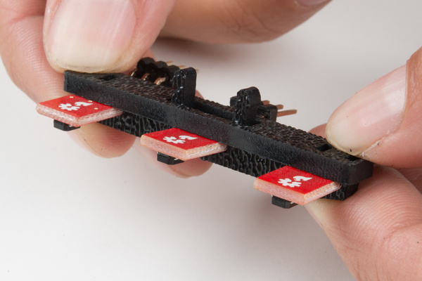
The next part is easier if you stabilize your Line Sensor sandwich (which we’re going to call a Line Sensor Array from here on out). Take a piece of electrical tape ~1.5” long, cut it in half, then wrap one piece around the entire sandwich in the gaps between the Line Sensors, like this:
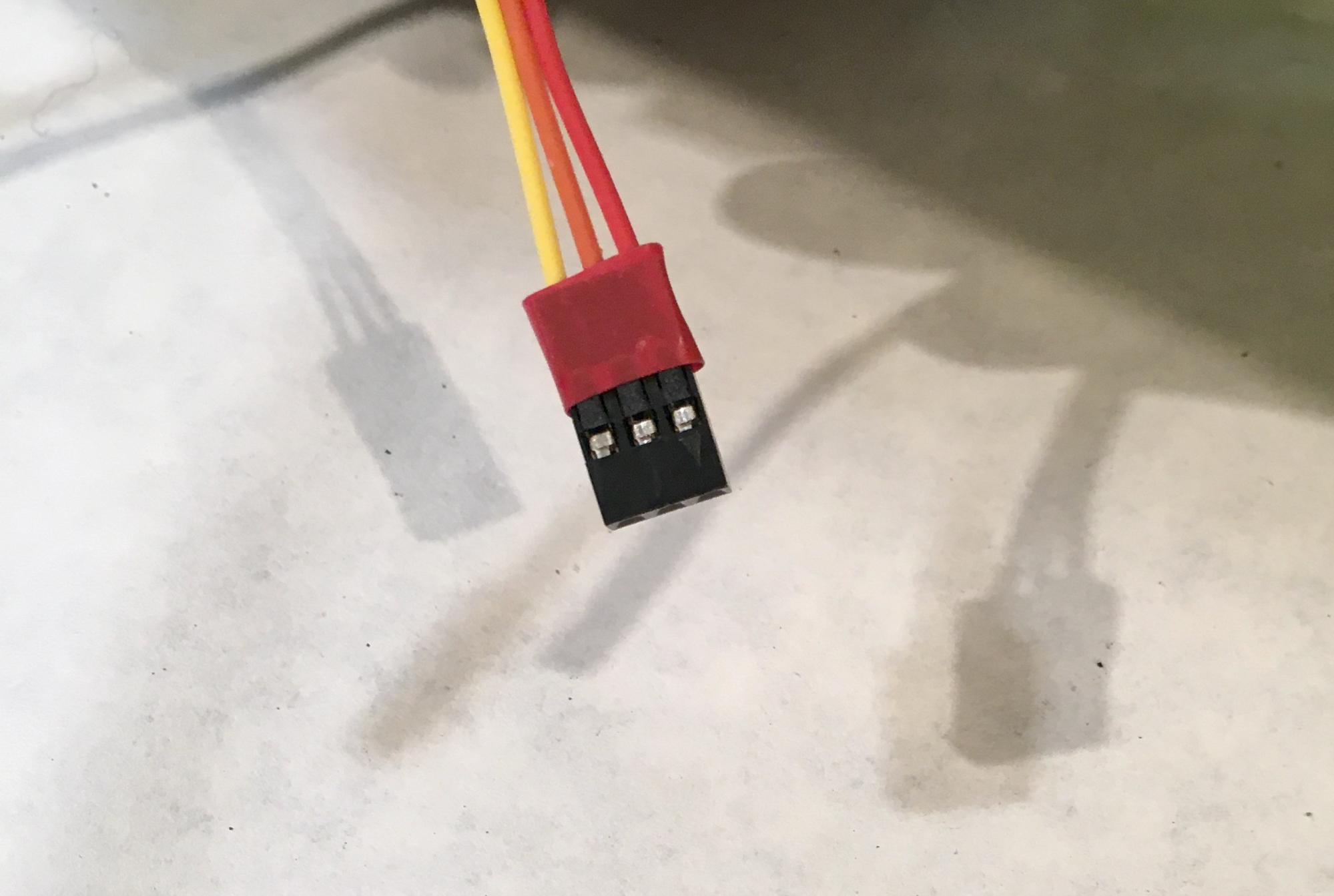
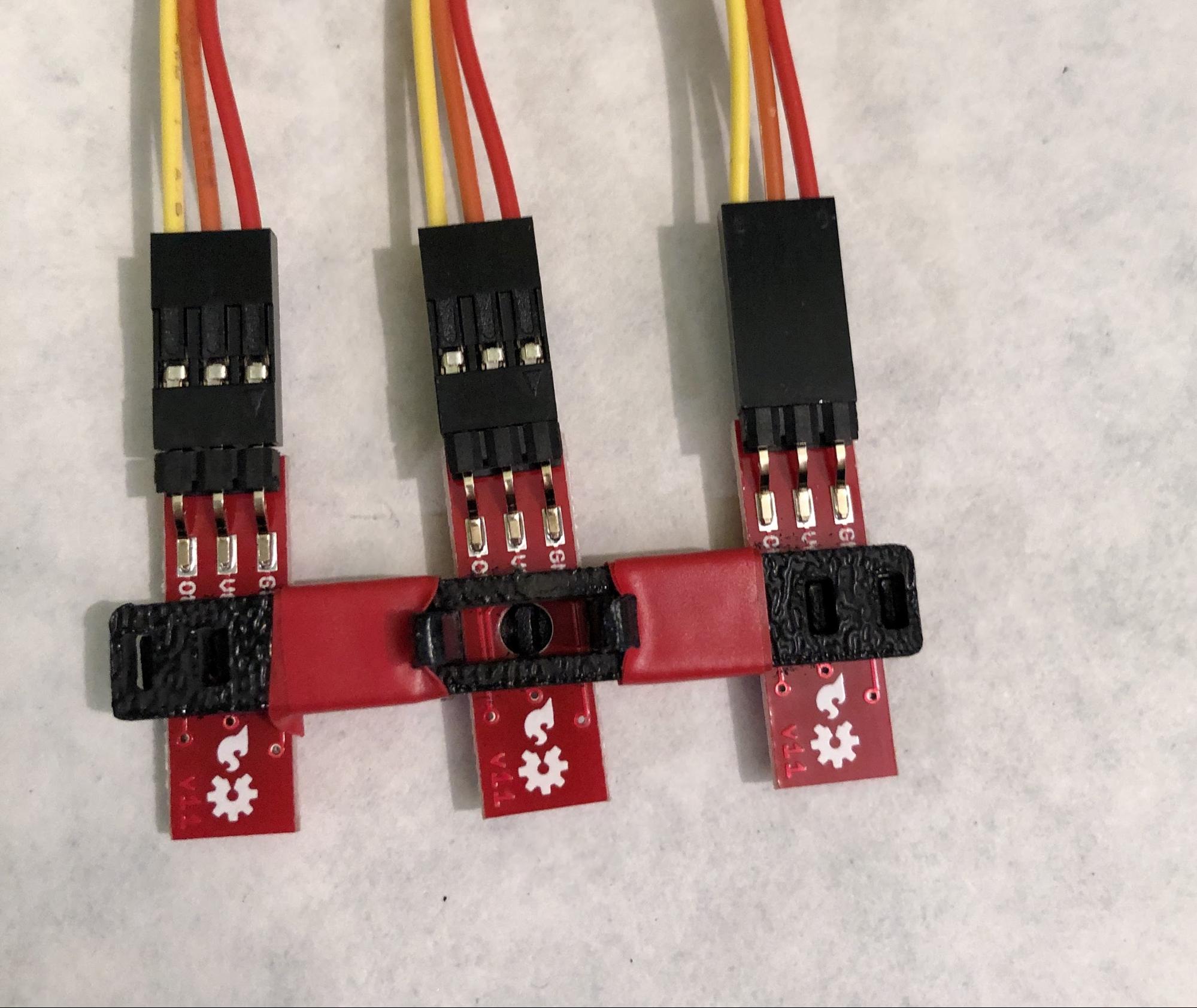
Next, you are going to connect a 3-Wire Jumper Cable to each of the Line Sensors. Note the color of the wire attached to each pin.
| Jumper Wire Color | RedBot Sensor - Line Follower |
|---|---|
| Red | GND |
| Orange | VCC |
| Yellow | OUT |
Attach all three cables to the three Line Sensors. When your Line Sensor Array is facing as shown in the picture below (the sensors face down here, as they will in the robot), the yellow wire should be on the left (on the “out” pin) and the red wire should be on the right (ground)
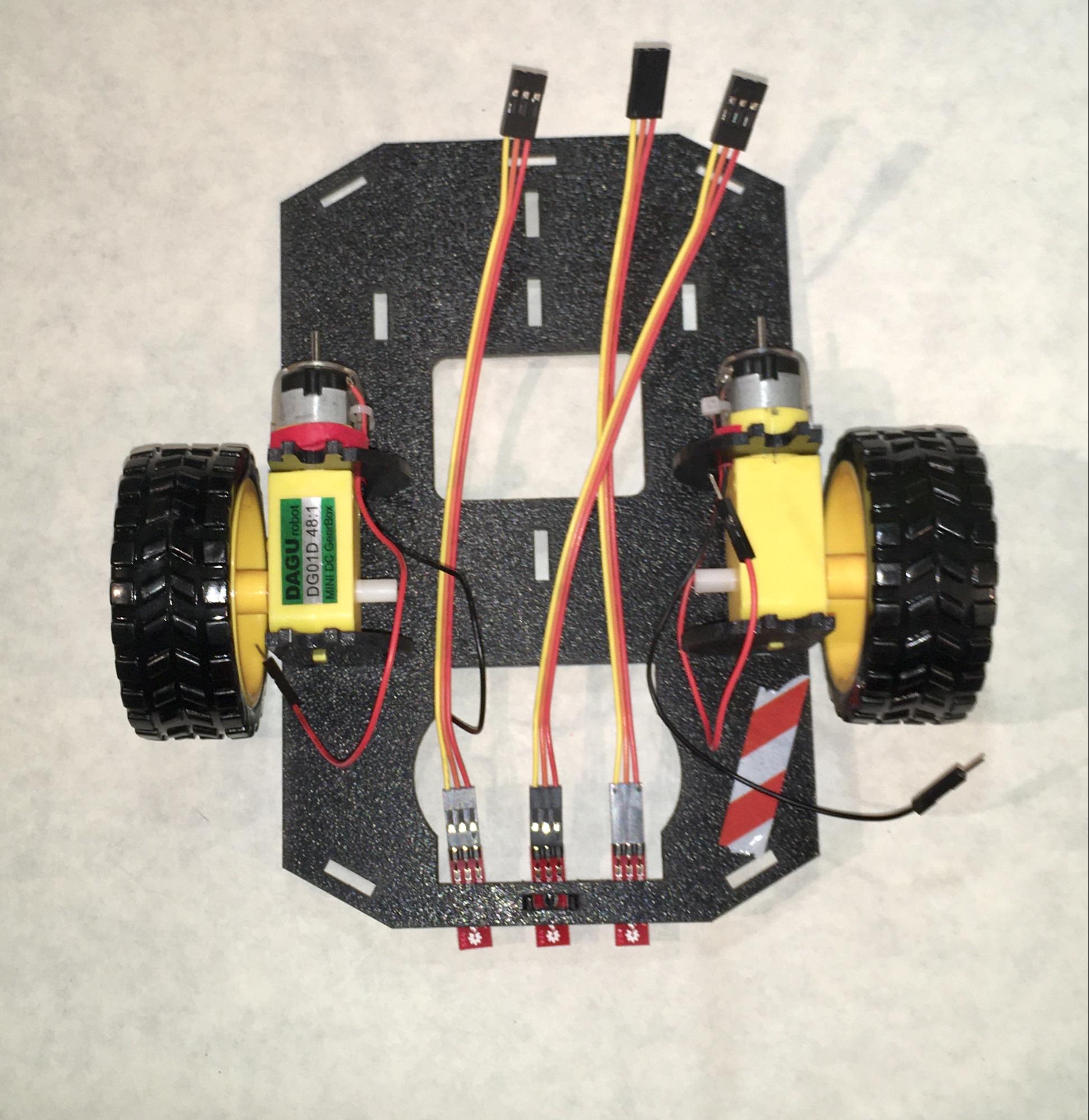
To attach the Line Sensor Array to the Chassis, locate the wide, rectangular slot near the front of the Lower Chassis and snap the Line Sensor Assembly in from the bottom side of the chassis. When you’re done the sensors will be facing the floor and the yellow wires will be on the left.
Route all three sets of wires through the large hole in the bottom chassis.
These wires will also have to pass through a single hole in the Top Chassis, and at that point it’s not easy to tell which line set of jumper cable bundles is which, so it helps if you mark the Middle Line Sensor cable before routing all the cables.
You need to mark the Middle Line Sensor cable because it and the Left Sensor bundle both get routed through the same hole on the top chassis, so they might get confused with each other. The Right Line Sensor goes through a different hole, so there’s no potential for confusion there.
The easiest way to mark the Middle Line Sensor cable is to cut a small piece of electrical tape (~.25”) and wrap it around the piece of plastic that’s at the free end of the cable bundle attached to the Middle Line Sensor.
The Middle Line Sensor cable is marked with electrical tape.