GNSS Timing Breakout - ZED-F9T (Qwiic) Hookup Guide
 Nate,
Nate,  El Duderino
 Introduction
Introducing the SparkFun GNSS Timing Breakout - ZED-F9T (Qwiic), a unique entry into SparkFun's GNSS catalog featuring the ZED-F9T GNSS receiver from u-blox. The ZED-F9T provides up to 5 nanosecond timing accuracy under clear skies with no external GNSS correction making it perfect for applications where timing accuracy is imperative. Need an extremely accurate time reference to maximize the efficiency of your IoT network of 5G devices? The GNSS Timing Breakout - ZED-F9T could be the perfect solution.
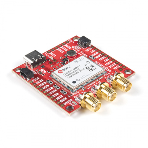
This breakout shares a similar design as the SparkFun GPS-RTK-SMA Breakout to create a small but comprehensive development tool for ZED-F9T. The design includes a USB-C connector for primary power and communication, two Qwiic connectors for communicating over I2C using the SparkFun Qwiic system, three SMA connectors for the antenna and timing pulse signals as well as a host of PTH pins allowing direct interaction with most of the ZED-F9T's pinout.
Required Materials
You will need the following materials along with the SparkFun GNSS Timing Breakout - ZED-F9T (Qwiic) to follow along with this tutorial.
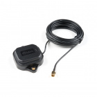
GNSS Antenna
The ZED-F9T is a dual receiving GNSS receiver which means it can receive both L1 and L2 GNSS frequencies. To enable this, you will need an appropriate antenna such as those listed below:
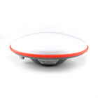
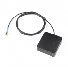
A low cost GNSS antenna will work and provide a basic fix but the advanced timing and positional accuracy features of the ZED-F9T will not be available without L2 support.
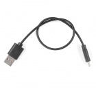
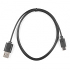
USB Cable
Basic use of the ZED-F9T either through a serial terminal or u-blox's u-center application needs a USB-C cable to connect the board to your computer:


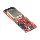
Arduino Examples Materials
For those who want to use the breakout board with the SparkFun u-blox GNSS Arduino Library, you'll need an Arduino microcontroller, Qwiic cable and USB-C cable to get started. We found the ESP32 works as a great transmitting option when creating a network of GNSS devices receiving time correction data from a ZED-F9T configured to act as a base station:


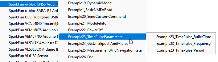
The SparkFun u-blox GNSS Arduino Library has a tremendous number of examples and features to demonstrate the power of our GNSS receivers. For the ZED-F9T specifically, be sure to view the Time Pulse examples. These will show you how to configure the time pulse settings for the two time pulse outputs.
While configuring the ZED-F9T over Qwiic from a microcontroller is pretty easy, many applications for timing require a set it and forget it mentality. Consider using u-center from u-blox to configure your ZED-F9T over USB and then saving the configuration to BBR (battery backed RAM) so that the module comes on with the same settings at the next power on.
Recommended Reading
Before getting started with the GNSS Timing Breakout you may want to read through these tutorials if you are not familiar with the concepts covered in them:
GPS Basics
Getting Started with U-Center for u-blox
Hardware Overview
Let's take a closer look at the ZED-F9T and other hardware present on the SparkFun GNSS Timing Breakout - ZED-F9T (Qwiic).
ZED-F9T GNSS Timing Module
The ZED-F9T is a multi-band GNSS receiver that excels at timing accuracy with the capability to achieve 5 nanosecond (ns) timing accuracy with a standard position lock.
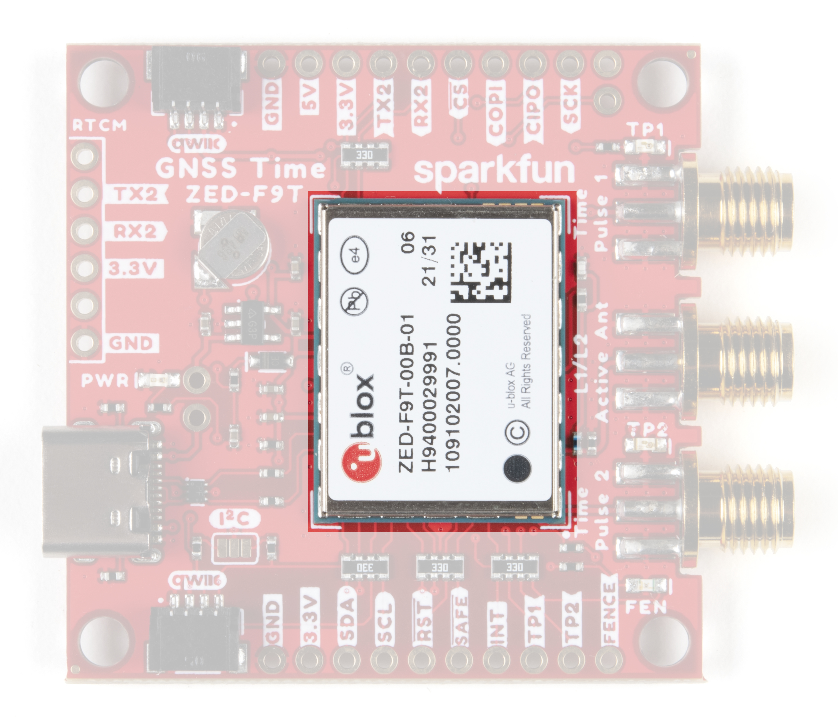
The ZED-F9T needs a clear view of the open sky to reduce the timing error to 5ns but requires no external correction. The module also features a Differential Timing Mode where correction data is shared between neighboring ZED-F9T receivers configured in a communication network. When configured properly in a communication network, the module can reduce timing errors to 2.5ns.
The GNSS Timing Breakout specifically uses a ZED-F9T-00B version of the module supporting L1/L2/E5b bands. The ZED-F9T operates on all major constellations (GPS, GLONASS, Galileo and BeiDou) concurrently making it extremely versatile and able to retain its timing precision even the module loses lock with one or more of the visible constellations.
The ZED-F9T also supports the creation of up to four geofence areas, security monitoring and detection systems that, when paired with an IoT controller, can send this data to the user. On top of all that, the ZED-F9T also has an integrated logging system users can configure to store position fixes and arbitrary byte strings in the receiver's Flash memory.
For a detailed overview of the module, these integrated systems and how to use them, refer to the datasheet and integration manual.
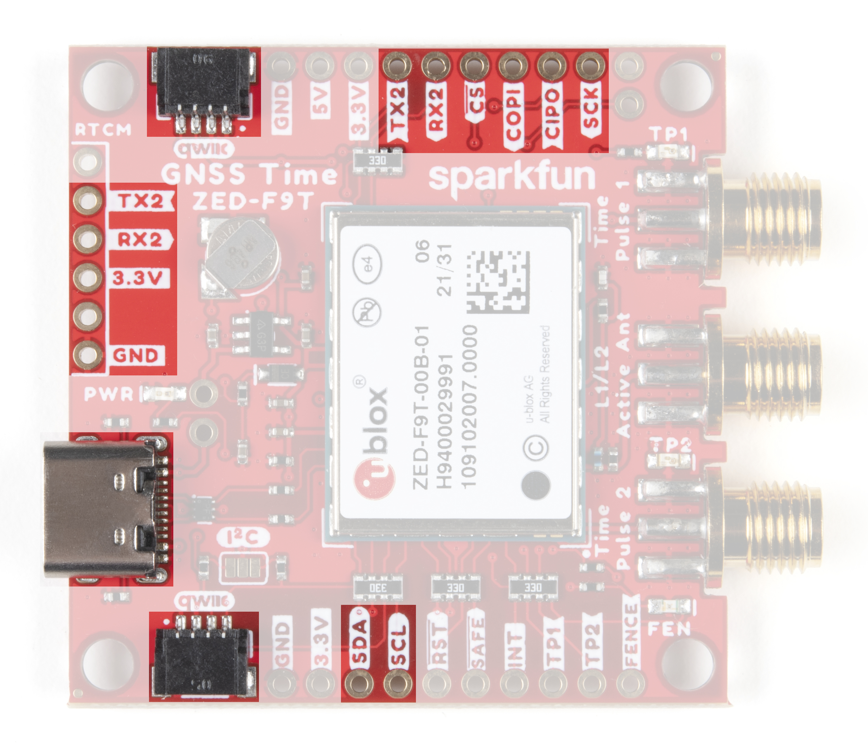
Communication Interfaces
The ZED-F9T features standard communication interfaces including USB, two UARTs, SPI and I2C. USB and UART2 have dedicated pins. UART1, SPI and I2C share pins and are selected by the state of the Interface Select pin (labeled D_SEL). The D_SEL pin is left open/"high" by default to enable UART1 and I2C and disable SPI. The shared pins are outlined below:
Default (D_SEL = 1/HIGH)
- TX
- RX
- SDA
- SCL
Alternate (D_SEL = 0/LOW)
- SPI CIPO
- SPI COPI
- SPI CS
- SPI CLK
USB
The ZED-F9T USB interface is routed to a USB-C connector. The USB acts as both a power input as well as a serial interface to quickly connect the module to u-blox's u-center software to configure the module and view NMEA sentences. See Getting Started with U-Center for more information about using the GNSS Timing Breakout with u-center over USB.
UART/Serial
The breakout routes the ZED-F9T's two UARTs (UART1 and UART2) to PTH headers. UART1 acts as a typical serial interface for NMEA sentences or other data. UART2 is a dedicated interface for sending or receiving RTCM correction data. The default settings for both UARTs are 38400 baud, 8-bits, no parity bit, 1 stop bit.
I2C/Qwiic
The board connects the ZED-F9T's I2C interface to PTH headers as well as a pair of Qwiic connectors to make it easy to add the GNSS Timing Breakout into a chain of I2C devices using the Qwiic ecosystem. Note, the pull-up resistors for the Qwiic connectors are disabled by default. Close the I2C jumper on the back of the breakout to enable those pull-up resistors.
The default 7-bit unshifted address for the ZED-F9T is 0x42 but is fully adjustable using the appropriate commands. Refer to the Integration Manual for more information.
SPI
The ZED-F9T's SPI interface is also broken out but is disabled by default. Enable SPI communication for the ZED-F9T by tying the D_SEL pin to GND/0V. Reminder, enabling the SPI interface disables UART1 and I2C.
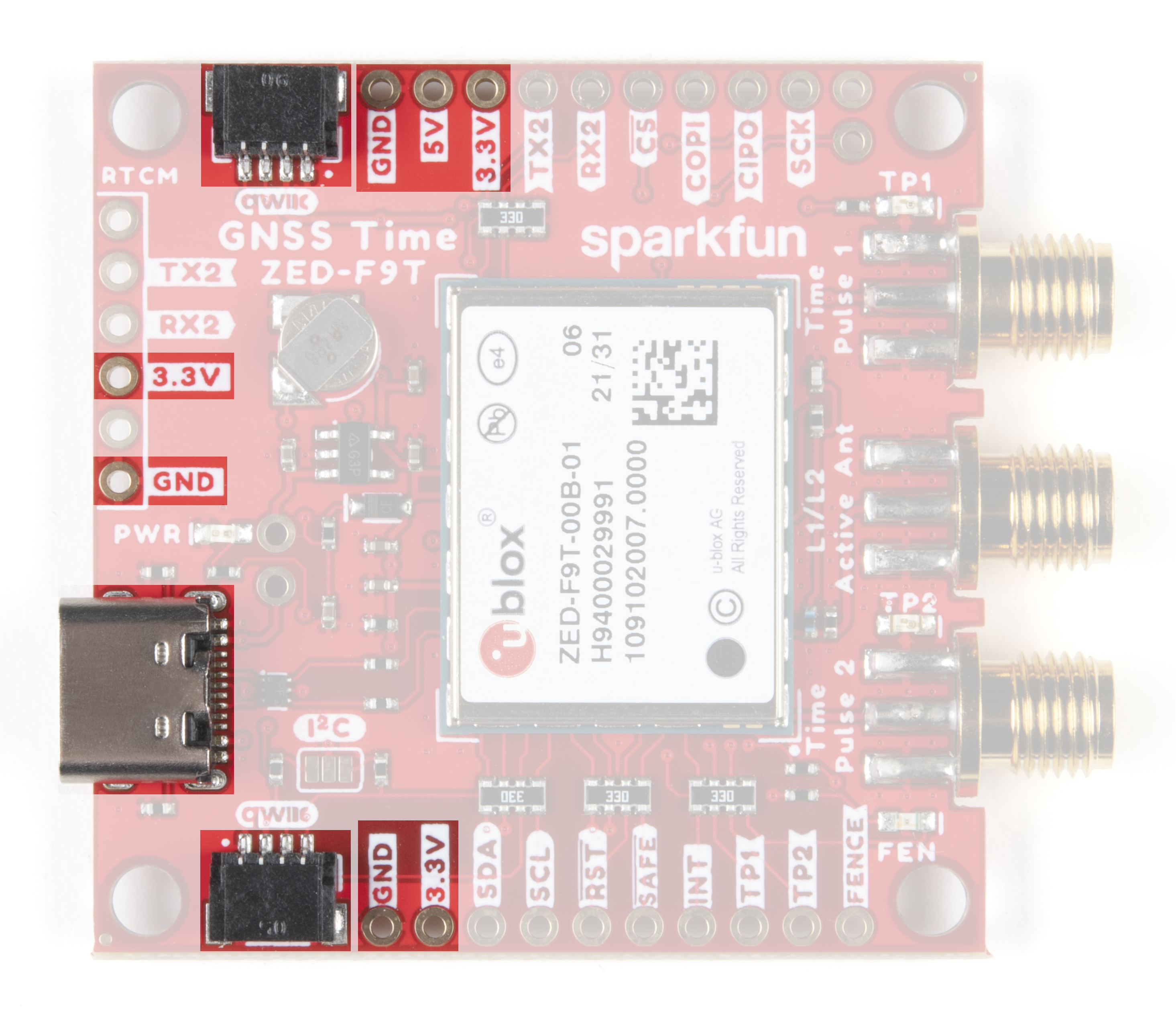
Power
Power for the GNSS Timing Breakout can be provided either via a USB-C connection or Qwiic connectors. The breakout also includes outputs for both 5V and 3.3V as well as a backup battery and charging circuit.
RTC Backup Battery Circuit
The board includes an RTC backup battery circuit to preserve settings and help with quick restarts and warm lock starts. The 1mAh battery can run the backup battery circuit on the ZED-F9T with no external power for roughly one day (24hrs) to preserve stored settings and let the module perform a hot start on restart.
SMA Connectors
The GNSS Timing Breakout has three SMA connectors. One for a GNSS antenna and two for the time pulse signals.
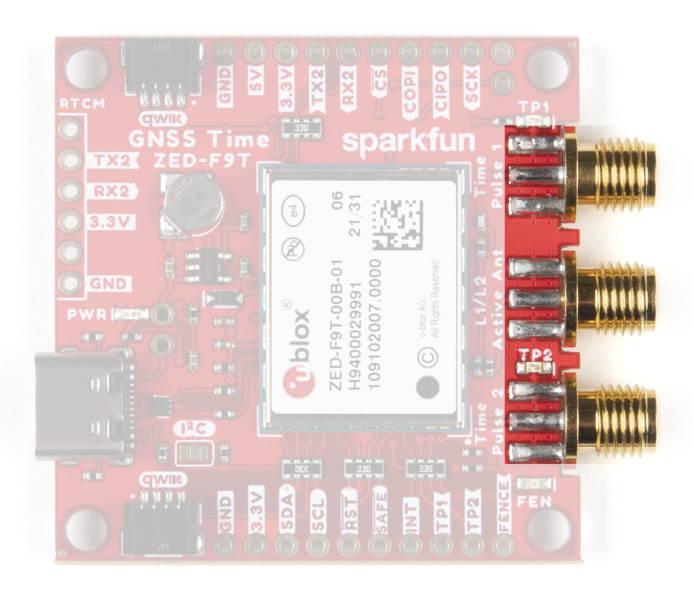
The time pulse signals can be connected to external devices to synchronize their action.
Control PTHs
The breakout also routes several control pins to PTHs from the ZED-F9T highlighted below:
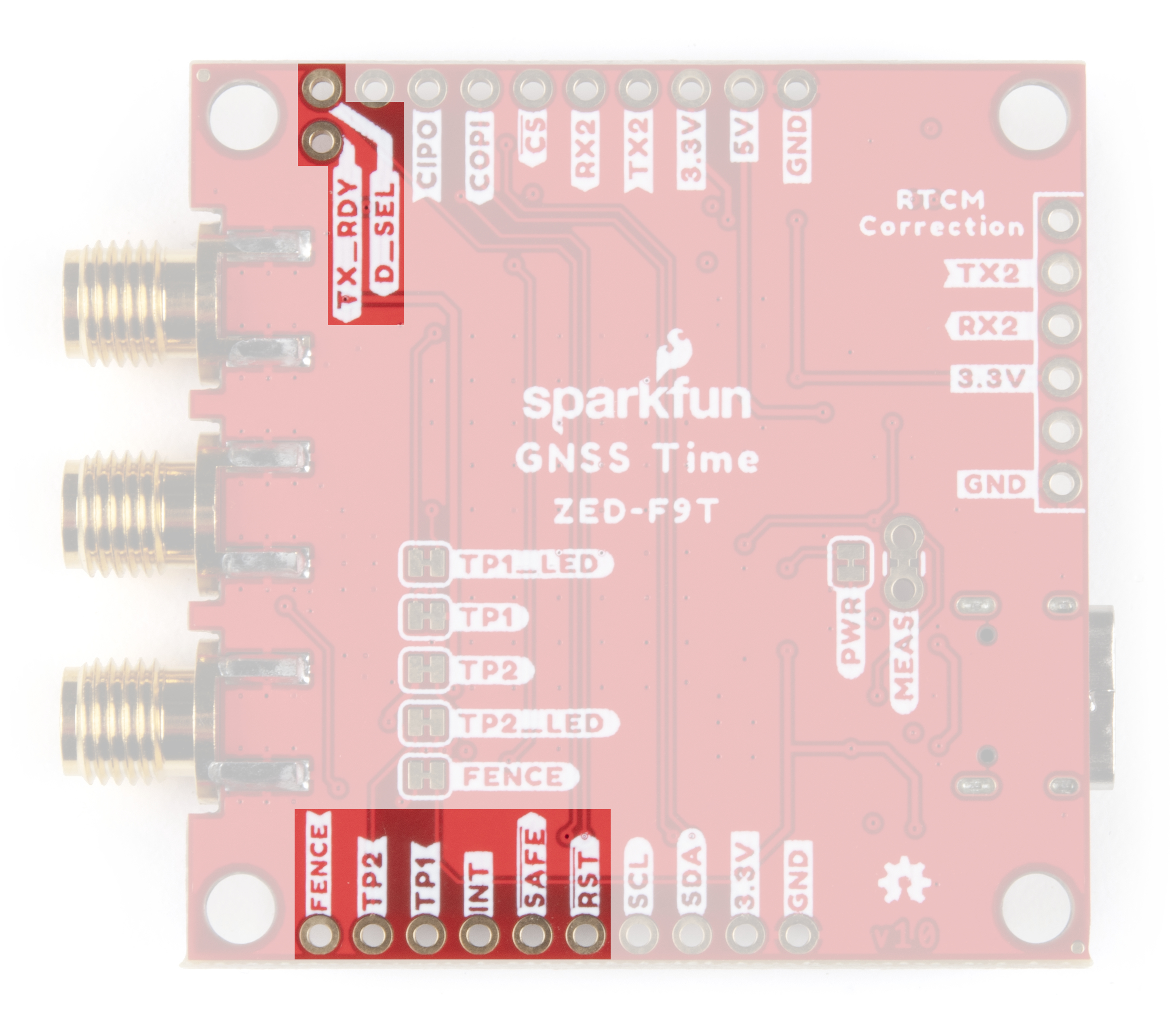
- RST: ZED-F9T reset pin. Pull the line LOW to reset the module.
- SAFE: Safeboot pin. Safeboot mode is required for firmware updates and generally should not be used or connected for normal operation.
- INT: Interrupt I/O pin. Use u-center to configure the pin to bring the module out of deep sleep or use it as an output interrupt for various operations.
- TP1: Timepulse 1 output signal.
- TP2: Timepulse 2 output signal.
- FENCE Geofence output pin. Configure with u-center to go either HIGH or LOW depending on settings when creating a geofence area. Use this to trigger alarms or actions when the module exits the defined geofence area.
- D_SEL: Interface selection pin. Default is Open/HIGH and selects UART1 and I2C interfaces. Connect to 0V/LOW to select SPI interface.
- TX_RDY: UART1 Ready to send pin.
LEDs
The breakout includes four status LEDs highlighted in the image below:
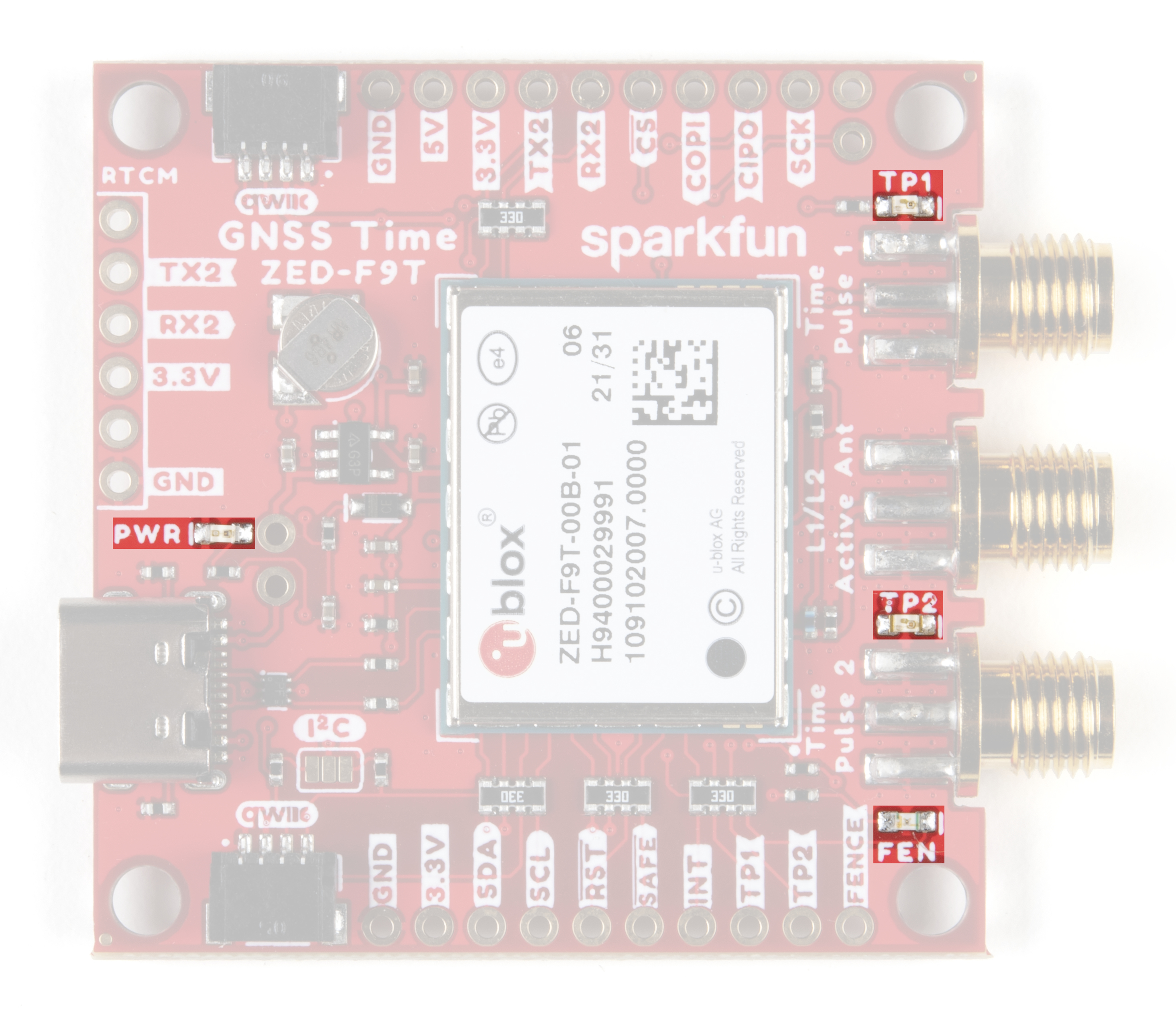
- PWR: Power LED. Illuminates whenever 3.3V is present from either USB or the Qwiic bus.
- TP1: Timepulse 1 status LED. Pulses on/off in sync with the signal from timepulse 1.
- TP2: Timepulse 2 status LED. Pulses on/off in sync with the signal from timepulse 2.
- FEN: Geofence status LED. Will turn on or off when the module exits the geofence area depending on settings.
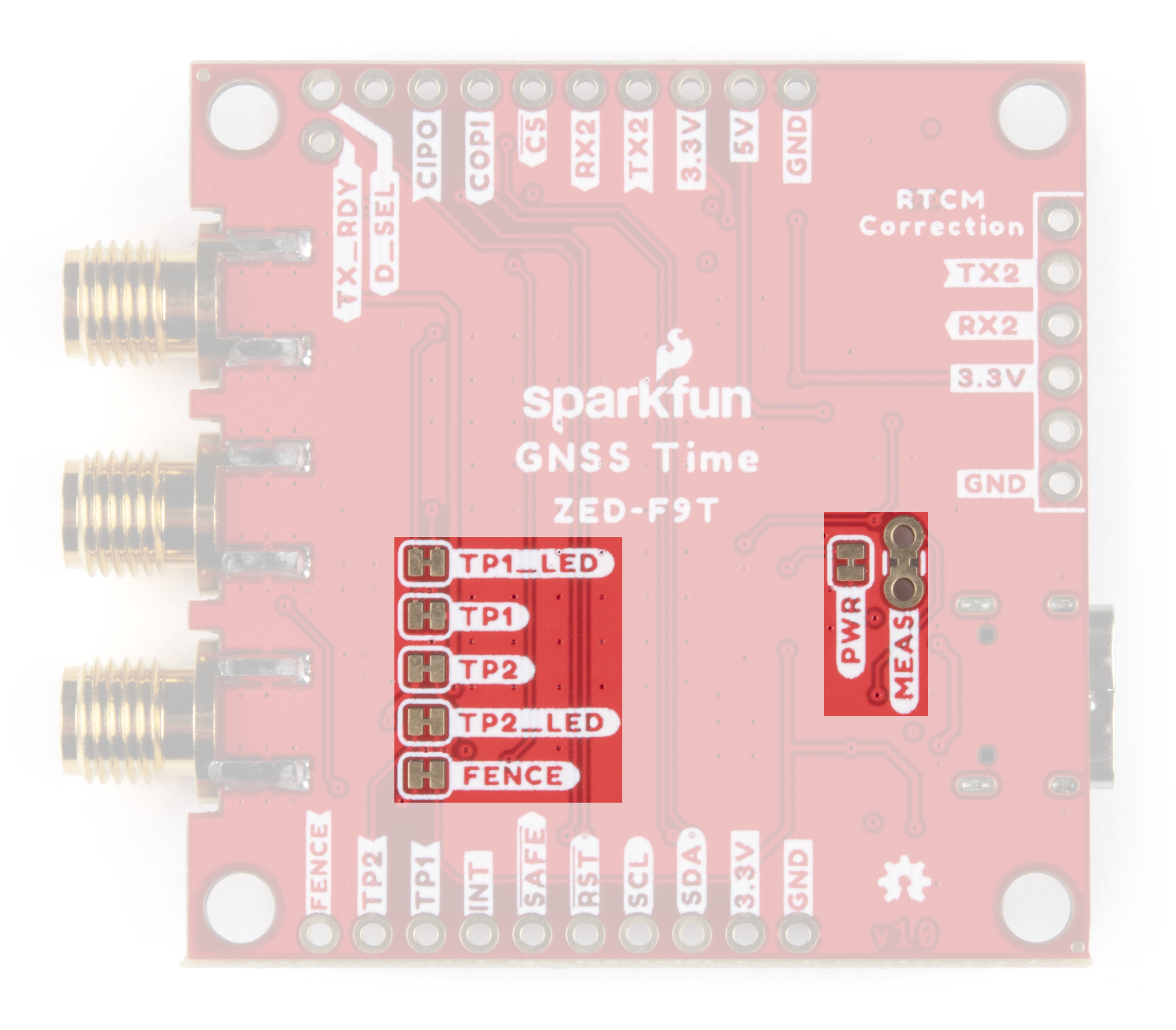
Solder Jumpers
The GNSS Timing Breakout has eight jumpers on board labeled I2C, MEAS, PWR, TP1, TP2, TP1_LED, TP2_LED, and FENCE. The table below outlines the functionality of each jumper and their default state.
| Jumper Label | Default State | Jumper Function |
|---|---|---|
| I2C | OPEN | Close to enable I2C pullups on bus. |
| MEAS | CLOSED | Open to measure current draw by the breakout from VBUS. Note, opening this jumper disables 5V input from USB |
| PWR | CLOSED | Completes Power LED circuit. Open to disable Power LED. |
| TP1 | CLOSED | Open to isolate the TP1 SMA connector from the TP1 PTH. Helps limit the stray time delay introduced by extra copper or externally soldered devices. |
| TP2 | CLOSED | Open to isolate the TP2 SMA connector from the TP2 PTH. Helps limit the stray time delay introduced by extra copper or externally soldered devices. |
| TP1_LED | CLOSED | Completes TP1 STAT LED circuit. Open to disable TP1 STAT LED. |
| TP2_LED | CLOSED | Completes TP2 STAT LED circuit. Open to disable TP2 STAT LED |
| FENCE | CLOSED | Completes the FENCE STAT LED circuit. Open to disable FENCE STAT LED. |
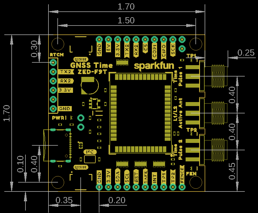
Board Dimensions
The GNSS Timing Breakout - ZED-F9T (Qwiic) measures 1.70" x 1.70" (43.18mm x 43.18mm) and includes four mounting holes that fit a 4-40 screw.
Hardware Assembly
The GNSS Timing Breakout requires very little assembly to initialize the device, get a lock and start receiving data. Setting up a device network to take advantage of the differential timing mode or using the GNSS Timing Breakout with the SparkFun u-blox Arduino library requires a bit more assembly and configuration.
Basic Assembly (Single GNSS Timing Breakout)
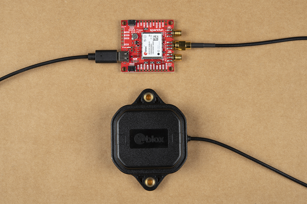
Initial setup and use of the GNSS Timing Breakout only requires a USB-C cable and GNNS antenna connected to the board. On first connection, drivers should automatically install. In case drivers do not install, head over to this section of our Getting Started with u-center for u-blox tutorial. Verify the port the device enumerated on and either open u-center (Windows only) to interact with and configure the device. Users who prefer to can use a serial terminal program and the Interface Description document.
With a clear view of the sky, the ZED-F9T should achieve a lock within 26s from a Cold Start (2 seconds from a Hot Start).
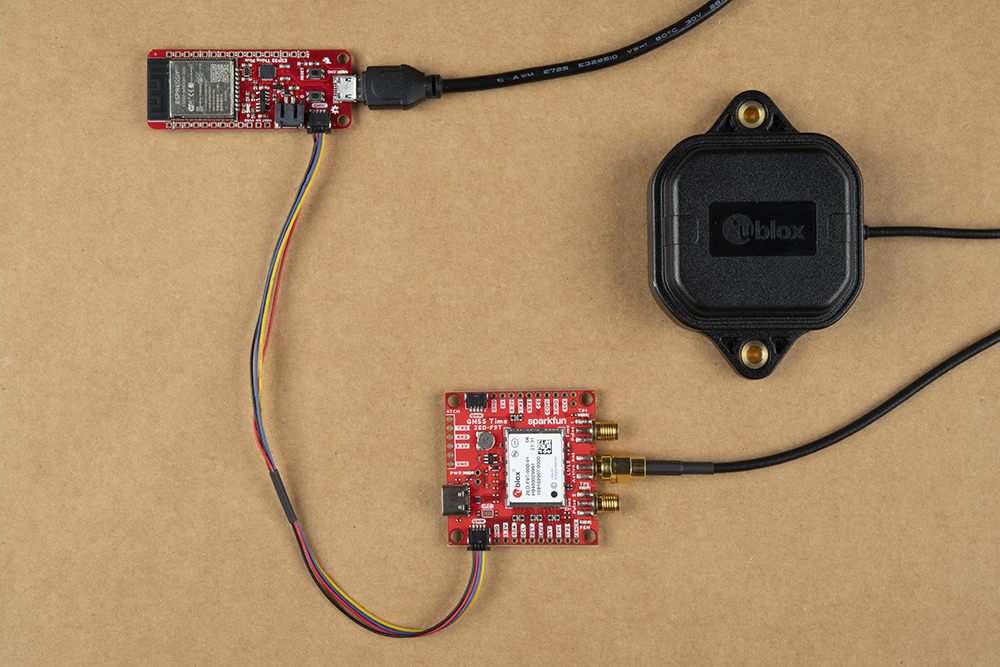
Arduino Assembly via Qwiic
Assembling the GNSS Timing Breakout into an Arduino circuit is easy thanks to the Qwiic system. Simply connect a GNSS antenna to the SMA connector and then connect the breakout to a Qwiic-enabled microcontroller like the SparkFun Thing Plus - ESP32 WROOM using a Qwiic cable.
Differential Timing Network
The GNSS Timing Breakout can be configured to act as a controller operating in reference station mode to provide timing correction data to a network of ZED devices. All that is needed here is 2 or more ZED devices with one acting as the reference station and a way to transmit the correction data (hard-wired, radio or WiFi.
For more information on setting up a Differential Timing Network using multiple devices, read on to the Using the ZED-F9T in Differential Timing Mode section of this guide as well as the Differential Timing Setup appnote from u-blox.
Arduino Examples
The SparkFun u-blox GNSS Arduino Library includes a host of examples to get users started with everything from a simple position lock to configuring and taking advantage of most features of all u-blox boards SparkFun carries. In this section we'll take a closer look at the examples demonstrating how to set up and use both time pulse signals on the ZED-F9T.
The SparkFun u-blox Arduino library can be downloaded with the Arduino library manager by searching 'SparkFun u-blox GNSS v3' or you can grab the zip here from the GitHub repository to manually install.
Time Pulse Parameters Example
The u-blox GNSS Arduino Library includes a set of three examples, "Example 23 - Time Pulse Parameters" for configuring and using the time pulse pins on the ZED-F9T and other u-blox modules capable of outputting time pulse signals. Open the examples by navigating to **File > Examples > SparkFun u-blox GNSS v3 > Basics > Example23_TimePulseParameters and select one of the three "sub" examples:
- Example23_TimePulse_Period - Demonstrates how to change the time pulse parameters and configure the time pulse pin(s) to produce a 1 second pulse every 30 seconds.
- Example23_TimePulse_Frequency - Shows how to adjust the time pulse parameters and configure the Time Pulse pin(s) to produce a 1kHz square wave.
- Example23_TimePulse_BulletTime - Demonstrates how to configure the Time Pulse pin(s) to produce a pulse once per second with an adjustable delay. You could use this to trigger multiple cameras and replicate the "bullet time" effect.
Open one of the examples, select your Board and Port and upload the code. Open the serial monitor with the baud set to 115200 to view the print out and confirm the time pulse pin(s) was configured and settings saved properly.
Using the ZED-F9T in Differential Timing Mode
The receiver has two time pulse signals, each with an accuracy of 5ns. These signals can be configured to have a frequency 0.25Hz to 25MHz with configurable pulse width and polarity. These tightly coupled signals make the ZED-F9T an excellent source as a time base.
Additionally, multiple ZED units can be synchronized by transmitting correction data from a control unit to multiple peripheral units. This allows multiple units, up to 20km (12 miles) apart to have synchronized time pulses with 2.5ns relative accuracy. In other words, differential timing mode will improve the phase alignment of the time pulse between units (and you can have 2 or 20, doesn't matter).
Setup Considerations
If you're familiar with GNSS RTK and base/rover setups the ZED-F9T is very similar. We will be scratching the surface so if you need additional information be sure to check out What is RTCM? and How to Setup a Temporary Base.
The purpose of a GNSS timing reference station is to not move. Once you tell a receiver that it is a reference station (ie, not moving) it will begin to look at the satellites zooming overhead and calculate its position. As the environment changes the signals from the GNSS (Global Navigation Satellite System - the collective term for GPS, GLONASS, Beidou, Galileo satellites) network change and morph. Because the base knows it is motionless, it can determine the disturbances in the ionosphere and troposphere (as well as other error sources) and begin to calculate the values needed to correct the location that the satellites are reporting to the actual location of the base station. These values are unsurprisingly called ‘correction values’ and are encoded into a format called RTCM. (RTCM stands for Radio Technical Commission for Maritime but is just a name for a standard akin to "802.11". Don’t worry about it.). You will often see the term RTCM3 being used; this is simply correction data being transmitted using version 3 of the RTCM format.
For specifics of configuring the ZED-F9T for reference station mode, please see the ZED-F9T Differential Timing Setup app note from u-blox. This will walk you through how to put a ZED-F9T into stationary mode. Once complete this unit will begin producing RTCM packets once per second.
Once packets are being produced, determine how the ~550 bytes per second will be delivered to the peripheral units to be synchronized. Typically, these packets are pushed to a NTRIP caster over an internet connection (you can read here about Setting up an NTRIP Caster). Alternatively these packets can be broadcast over serial modem radios, buried cable, or any other back haul option capable of supporting ~1kB/s. We've found that using an ESP32 along with a Qwiic connection and WiFi makes setting up an NTRIP connection enticingly easy.
Once a reference station has been setup, the peripheral ZED-F9Ts simply need to access these RTCM packets and have them fed into the module. Generally, this is done over UART2 but can be done over USB, I2C, UART1 or SPI. Don't worry, we've got Arduino examples demonstrating both NTRIP Client and Server that can be leveraged for the ZED-F9T. And if Arduino and RTK2Go are not your cup of tea, u-center has a built in Caster and Client that will make the connection between multiple units over USB using their Windows application.
Resources and Going Further
That's a wrap for this tutorial. For more information about the SparkFun GNSS Timing Breakout - ZED-F9T (Qwiic), check out the following resources:
- Schematic (PDF)
- Eagle Files (ZIP)
- Board Dimensions (PNG)
- Datasheet (PDF) (ZED-F9T)
- Integration Manual (PDF) (ZED-F9T)
- Interface Description Reference (PDF) (ZED-F9T)
- Differential Timing Setup AppNote (PDF) (ZED-F9T)
- u-center Software
- SparkFun u-blox GNSS Arduino Library
- GitHub Hardware Repository
For more information on setting up a GNSS Timing Breakout - ZED-F9T as a time base station and broadcasting RTCM data, head over to these tutorials:
- What is GPS RTK? - What is RTCM
- Setting Up a Rover Base RTK System - Setting Up a Temporary Base
- How to Build a DIY GNSS Reference Station:
Looking for inspiration for your next GNSS project? The tutorials below may help: