GPS Differential Vector Pointer
Introduction
In this tutorial you'll learn how to use GPS receivers to have two objects, a base and a target, point towards one another. This can be used to aim sensors, antennas, lasers, etc. from one object to another over long distances.
Project Background
GPS technology is a very useful and elegant technology. The satellites used in the GPS network do most of the work so that the GPS receiver can be made small and simple. As GPS technology becomes more and more accurate, applications in many areas have really taken off. Some of these include driver-less cars, mission planning for UAVs, assisted landing of commercial aircraft and many more. GPS receivers vary in cost depending on accuracy and what other functions they provide, so the right receiver needs to be chosen for the desired application. In this project, I am demonstrating that an expensive receiver is not necessary to create an amazing project.
This project began as a proof of concept for the ANACONDA 2014/2015 Aerospace Senior project whose mission was to:
“Design and construct an autonomous tracking and communication support system for an antenna to be used to track unmanned aircraft during flight.”
If you want to check out this and other projects, follow the link below to the CU senior projects page, and go to the 2015 projects page.
Project Overview
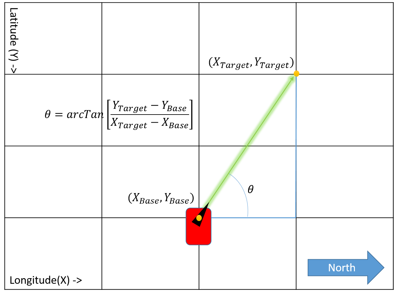
The underlying principle here is that, if two GPS locations are provided by two different receivers, a position vector can be calculated between them. This can be used to aim a directional antenna (or in the case of this project a laser) from one object (the base station) to the other object (the target) at any distance, which is only limited to your ability to provide the base station with the target's GPS location. The target's only purpose is to receives its GPS location, parse the data and send that back to the base station. The base station then receives the target's GPS location and compares it to its own GPS location to calculate the positional vector. The base station also includes a 180 degree servo and a laser, so the direction can be visualized.

Knowing the horizontal and the vertical difference between points, you can use the inverse tangent function to give you the pointing angle needed to control the mechanism. See the image below.
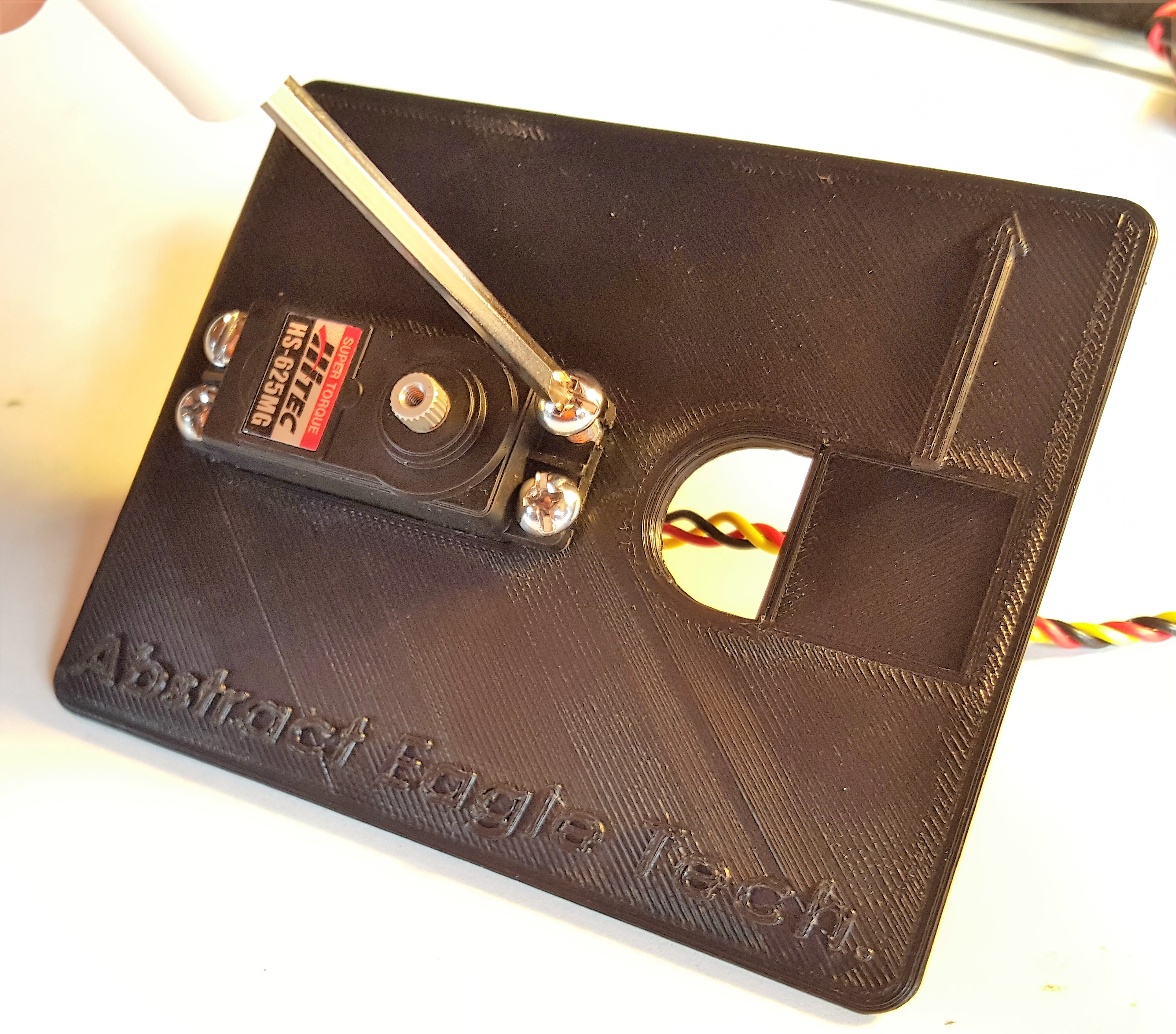
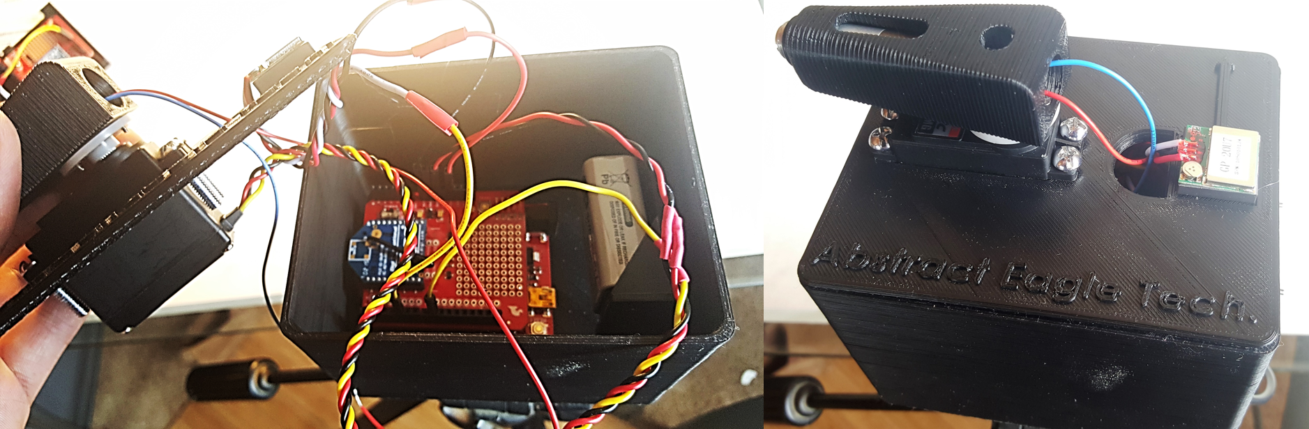
The final product looked like the following:
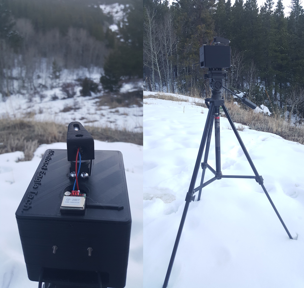
The image above shows the GPS antenna pointed down. Ideally, you would want to point the ceramic antenna facing the sky to receive the best satellite reception. In this tutorial, the satellites in view was sufficient enough for the project to function. Make sure to mount your GPS receiver with the antenna pointed toward the sky.
This tutorial will go over how to replicate this system.
Suggested Materials
To follow along with this tutorial, we recommend the following supplies:
Electrical Supplies
Here is a list of all the SparkFun materials you will need for this project:
Mechanical Supplies
You will need some hardware to mount electronics in the final system:
- Access to a 3D printer
- Tripod with universal camera mount platform
- Magnetic compass
- Mounting Hardware
- 4 X 8-32 Machine screws
- 3x 1/2” spacers with #5 sized through hole
- 3x 2-56 ½” Machine screws
- 3x 2-56 ¾” Machine screws
- 6x 2-56 Hex Nuts
- 6x 1-72 ½” Flathead screws
- 6x 1-72 Hex Nuts
- 2 x 0-80 Flathead screws
- 1 5/16th O-ring with 1/16th wall thickness or less
3D Models
A custom enclosure was created for each piece in this project. These files are provided in the link below, if you wish to download and print them. These files can also be found in the 3D Models section.
Suggested Reading
Before embarking upon this tutorial, you may find the following links useful:
Serial Communication
GPS Basics
XBee Shield Hookup Guide
Exploring XBees and XCTU
3D Models
For this project, the cases and laser mount were all created on a student edition of SolidWorks to be printed using a 3D printer. The printer used in this project is an XYZ da Vinci 1.0 AiO. There are four pieces that need to be printed for this project, and their files are included below, saved as .STL.
If you have not done so already, the 3D model files can be downloaded from the following link.
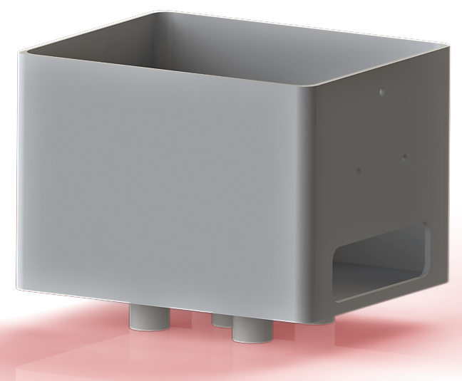
Target
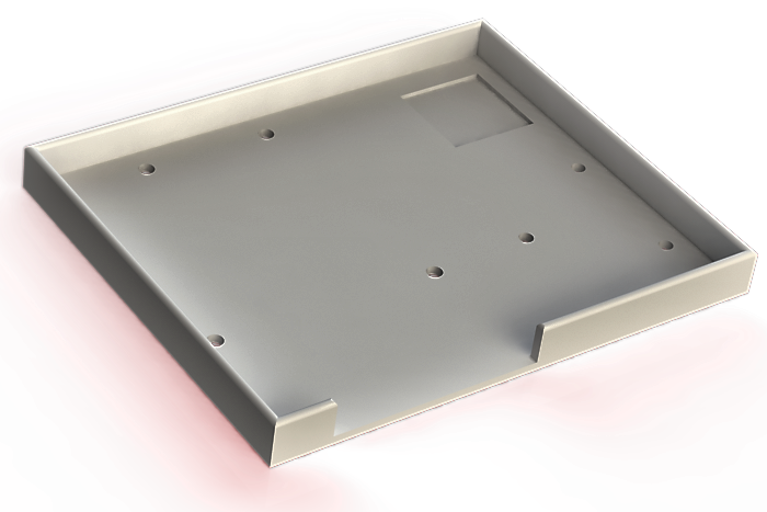
Base Bottom
Base Top

Laser Mount

Electronics Assembly
All the electronics in this project plug directly into pins on the XBee Shield (with the exception of the laser diode), which makes this part pretty straightforward. I have designed this mechanism so that the connections are not permanent and can be taken apart, but you can solder the connections instead, if desired.
The first step is to configure both XBees so that they are set up on the right channel. This is described in detail in this tutorial.
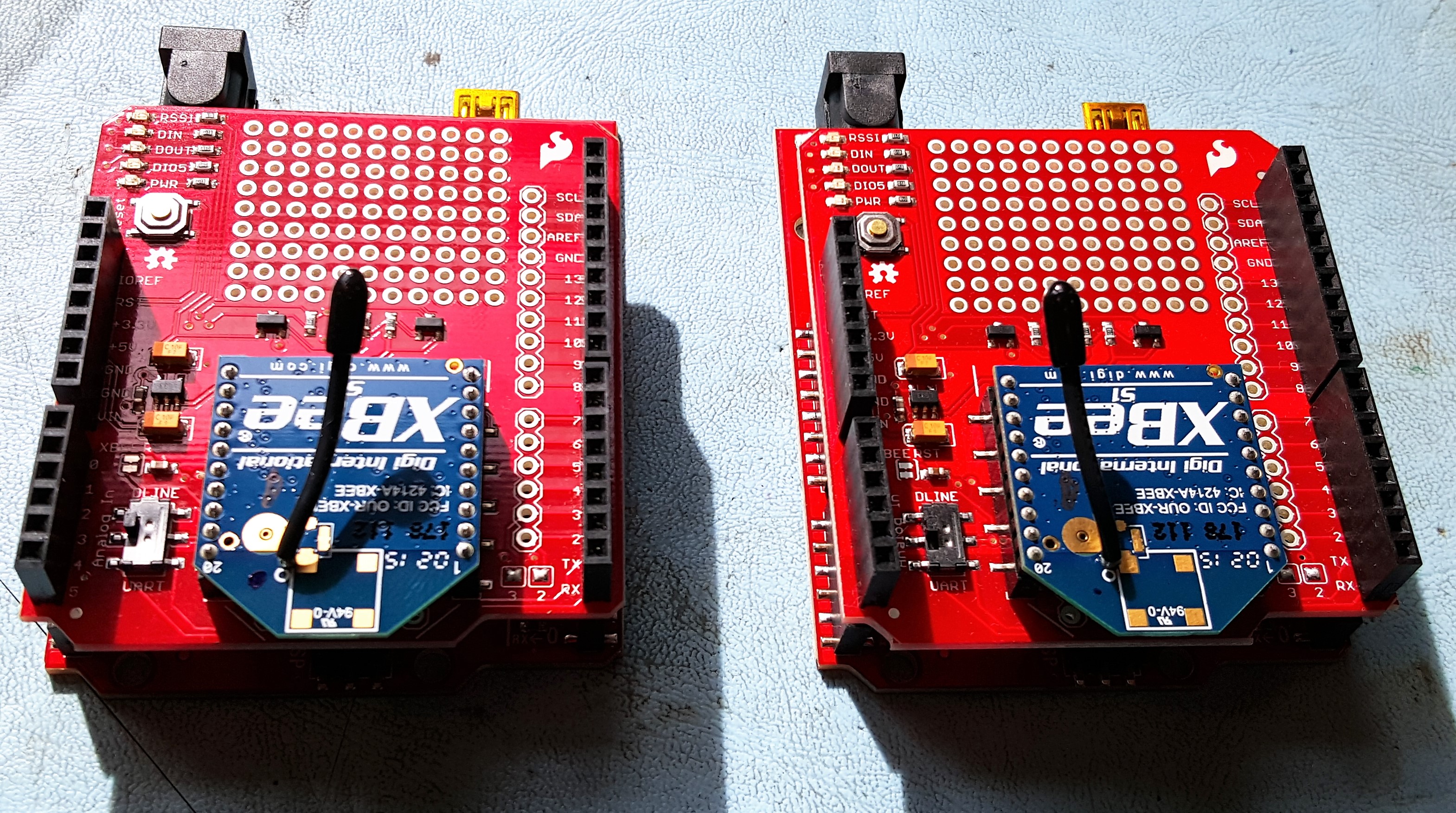
Once everything is configured, you will need to create two identical assemblies of the RedBoard with the XBee shields attached. Stackable headers will need to be soldered onto the XBee Shield, so that it can be mounted on top of the RedBoard and wires can still be attached. A detailed walk-through of this process is described here.
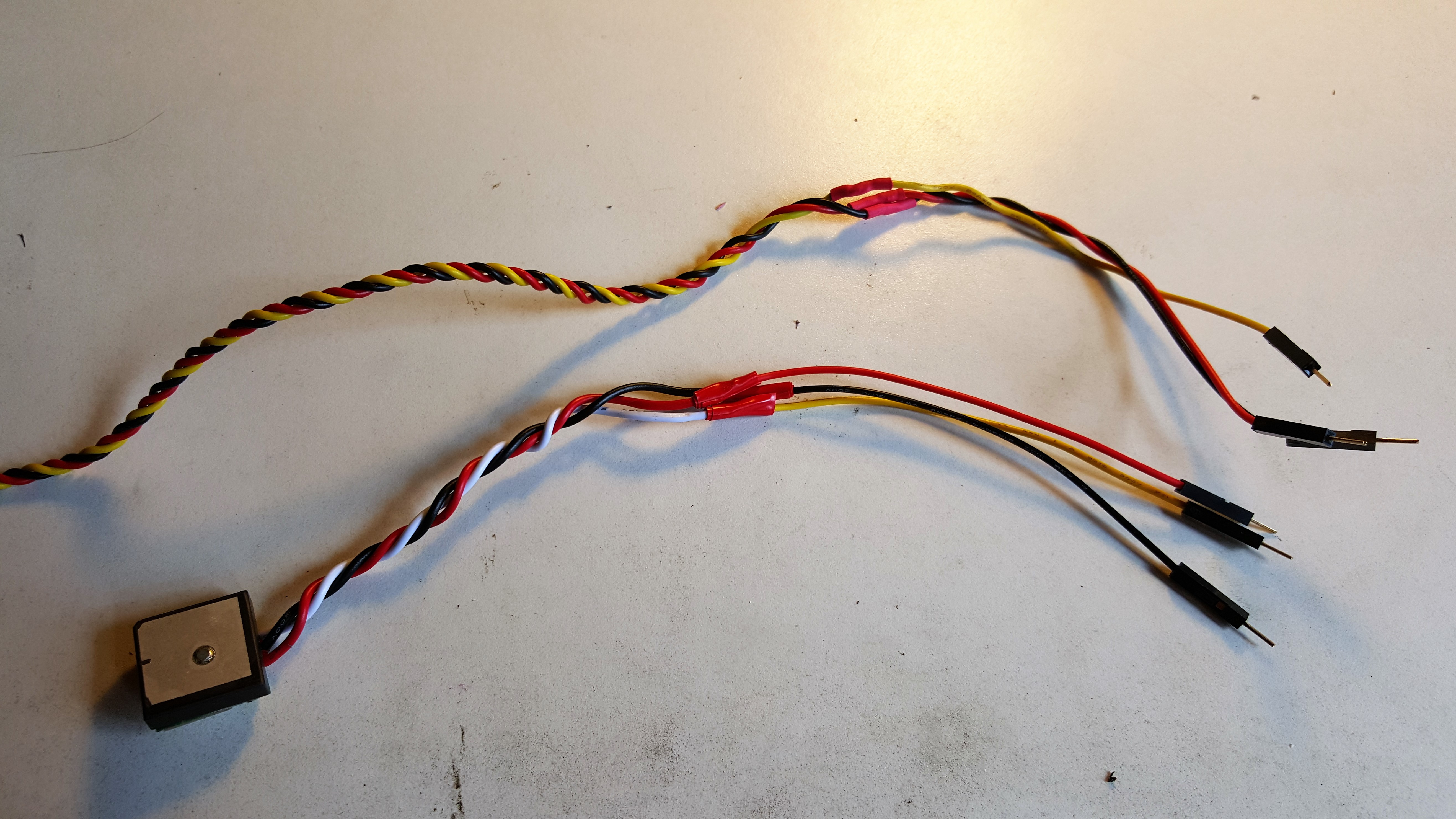
Next, prepare the wires of the two GPS receivers and the servo so they can easily be plugged into the shield. I cut off the existing connectors and soldered them to male jumper wires for easy pluggability. The wires for the target GPS receiver can be made shorter so you don't have excess wire. Make sure you leave enough length to reach the pins from where the receiver will be mounted.
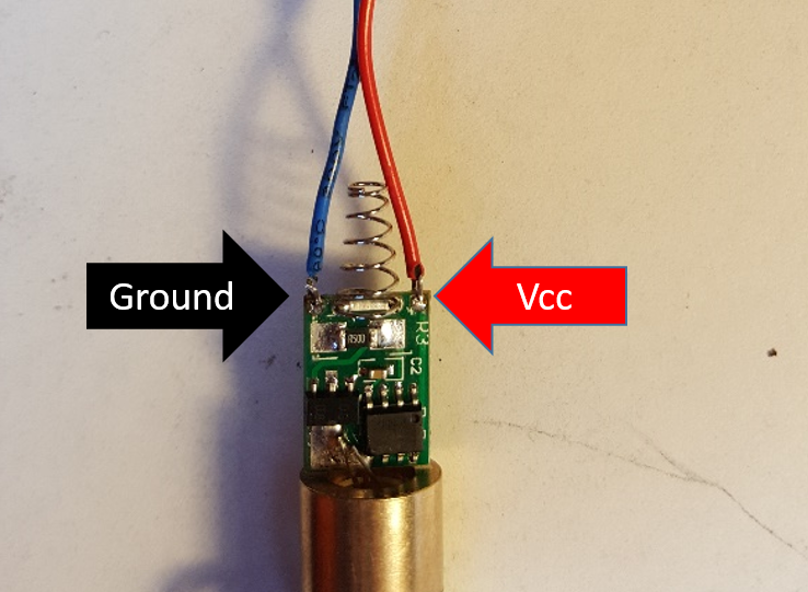
The last step will be to connect the Laser diode. To do this, you will first need to solder stranded wire to the two holes located on the laser PCB. Ensure they are attached to the correct pads, as shown here. Take care when soldering these pads as too much heat can damage the laser electronics.
Because the laser will be moving, these wires should be soldered rather than just plugged in. This will be done on the XBee shield used on the Base. The following diagrams show how everything should be connected. Note that the LED in the diagram represents the laser.

System Assembly
This section will cover how to install the electronics in the 3D printed enclosures.
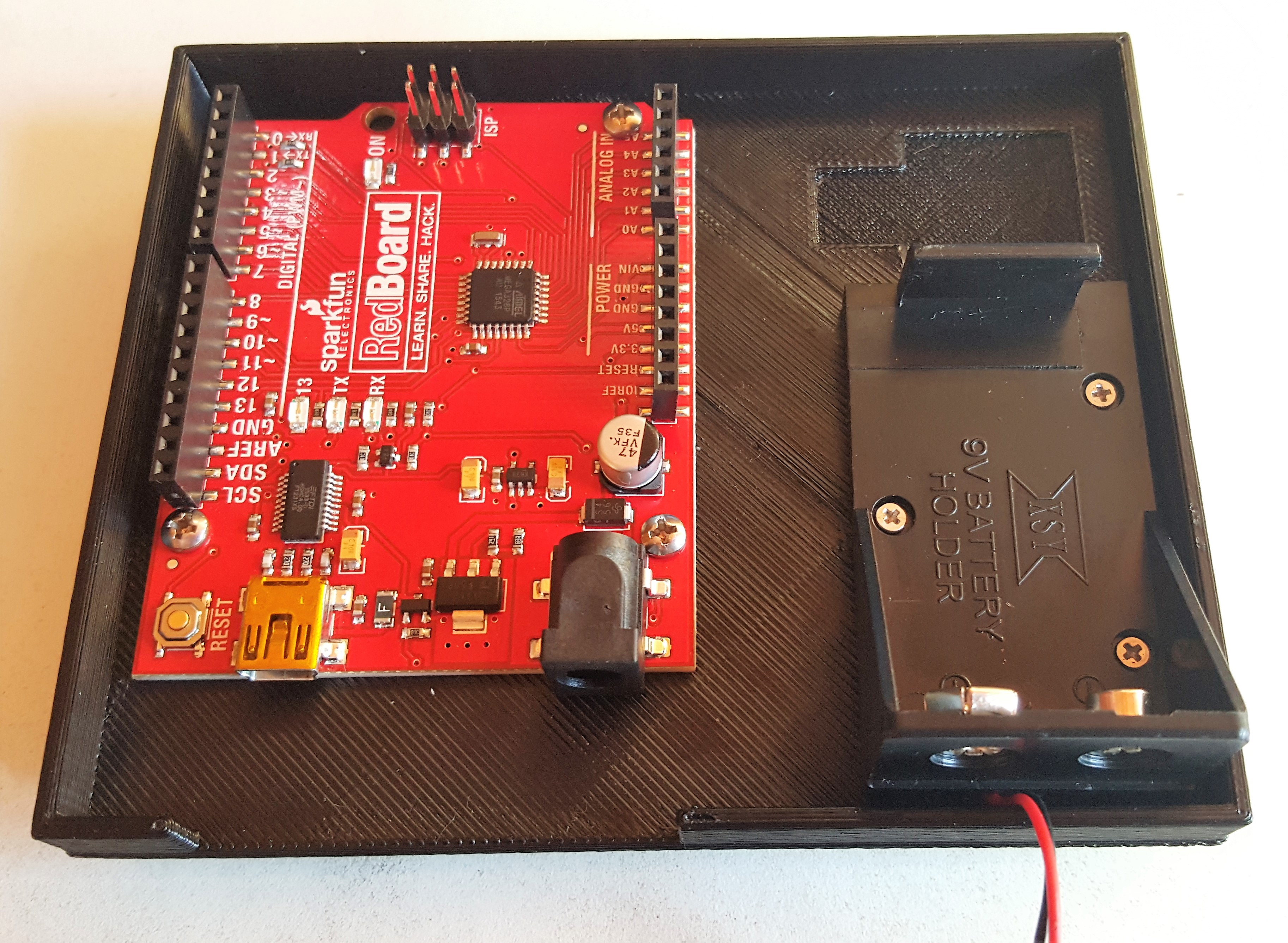
Base Station Bottom
Attach the RedBoard to the base using 32-56 ¾” machine screws with the three spacers in between so it is elevated off the bottom of the case. This is to ensure that the mounting hole is available, which you may need depending on your tripod mounting situation.
Connect the 9V battery. Mount the battery enclosure onto the holes located on the wall of case.

Depending on your tripod, this step may be different. The tripod used in this guide had a piece with the mounting screw that can be threaded into the available mounting hole and works quite nicely.
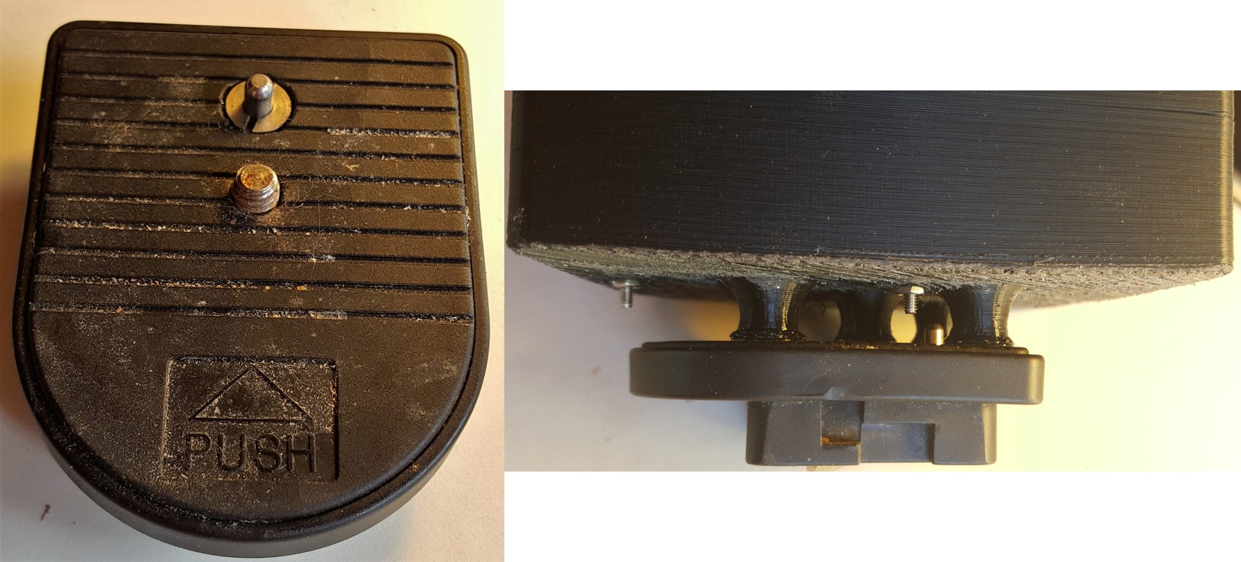
Base Station Top
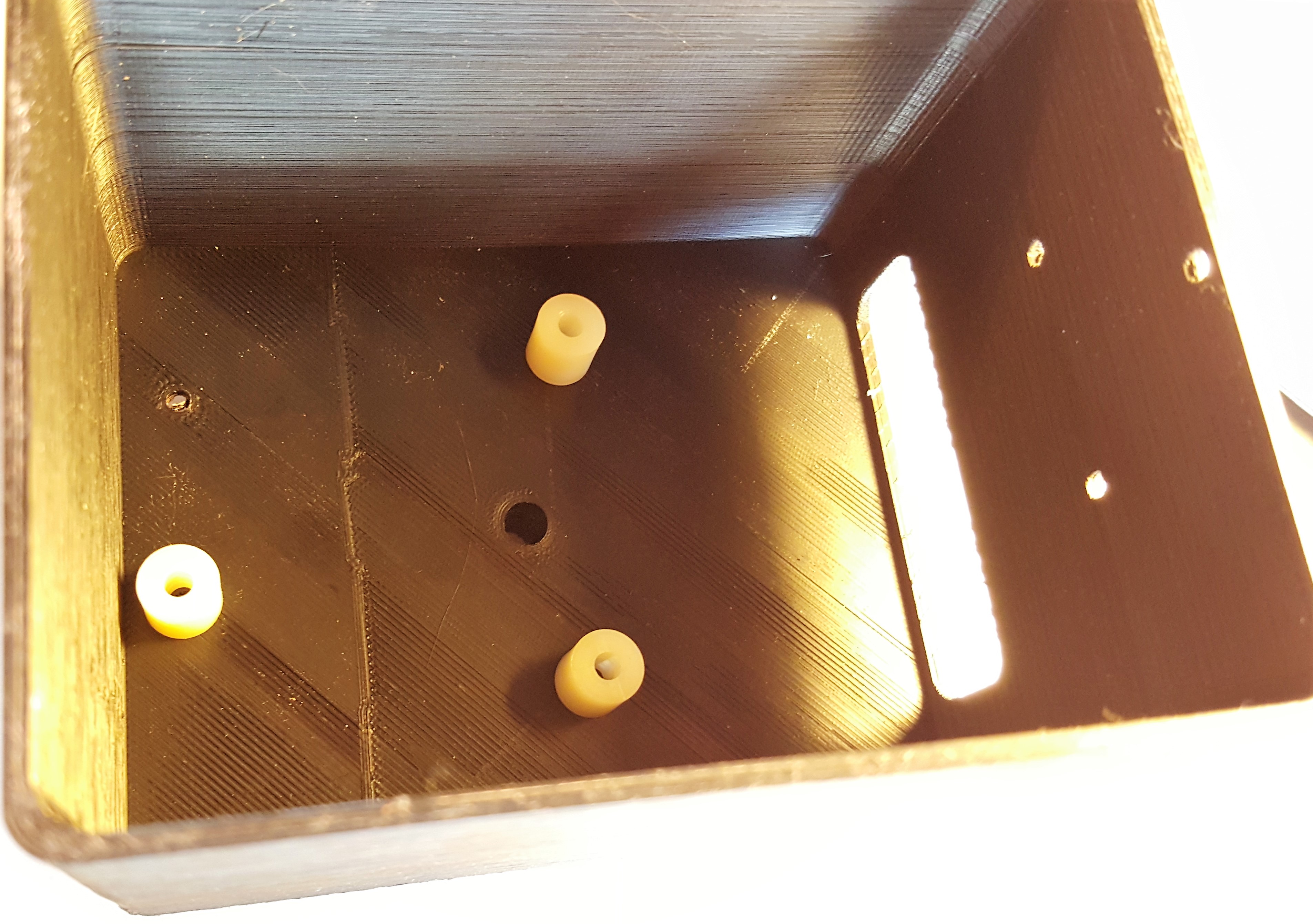
Place the servo in the available cavity with the gear closer to the GPS cavity. Once in place, screw the four 8-32 screws into the available holes on the servo. You shouldn't need nuts for the other side since the holes are close fit and the ABS used is soft and allows them to easily thread themselves into place. If the servo moves around too much, you can add nuts for stability.
Attach the circular servo disk (a.k.a. horn) to the laser mount aligning the hole on the bottom of the laser mount with the hole on the disk. Attach this by placing two 0-80 Flathead screws through the countersunk holes within the laser cavity. You may need to open up the holes on the circular wheel since they will be used as pins, and you will not be able to screw them in. These are to ensure that the two parts are connected in the right orientation, and, if loose, you may need to use an adhesive to attach these.
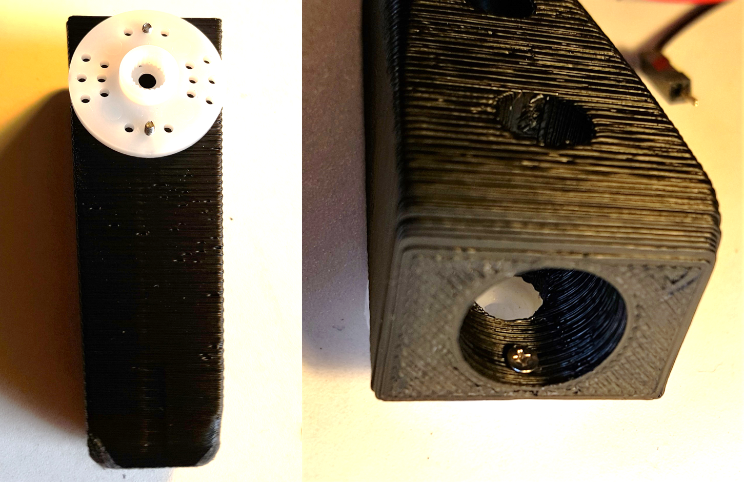
Next, attach this assembly to the servo. Slide the circular disk back onto the servo, then screw it to the servo, using to the available hole in the laser mount to access it with a screw driver.
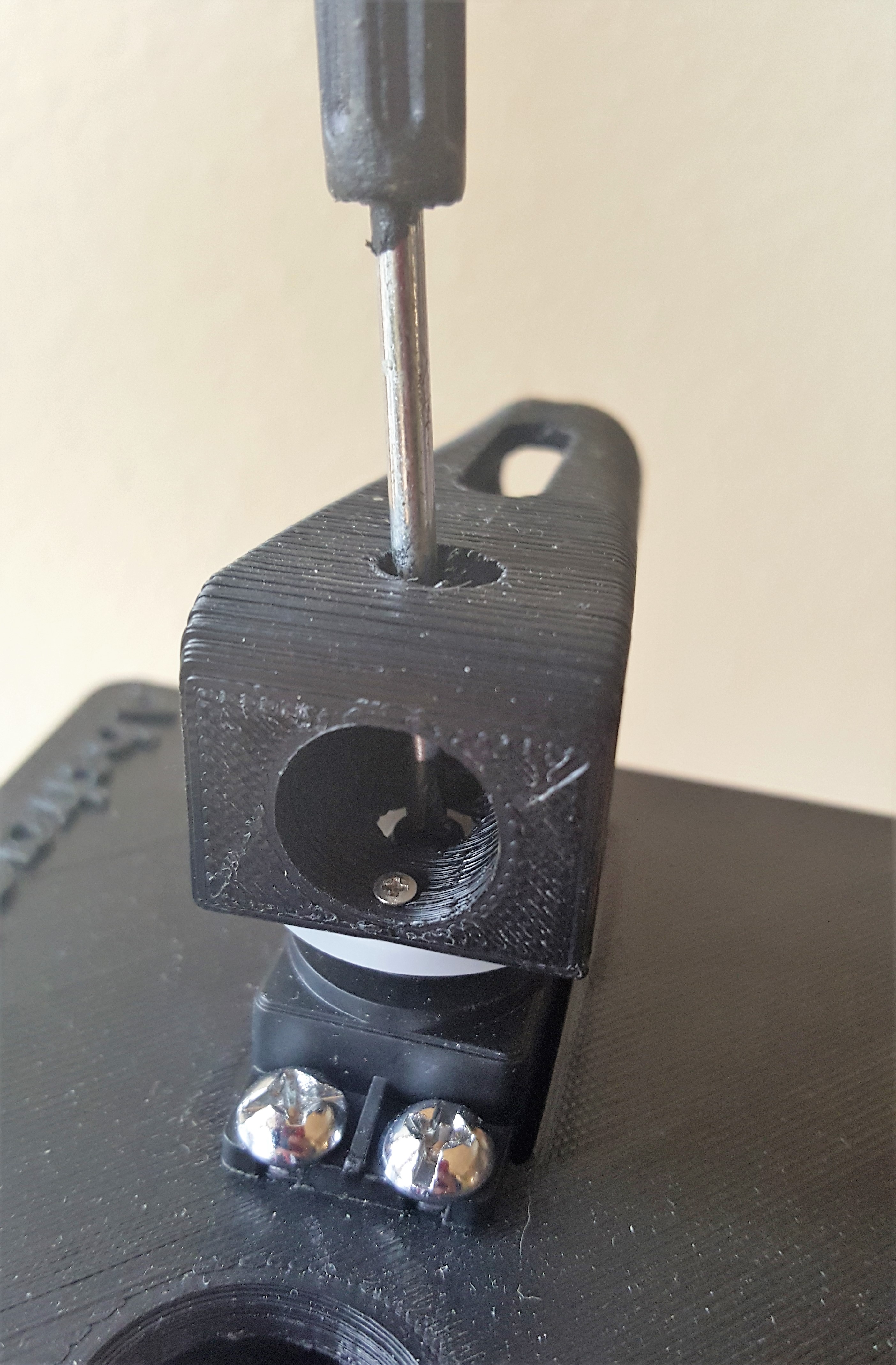

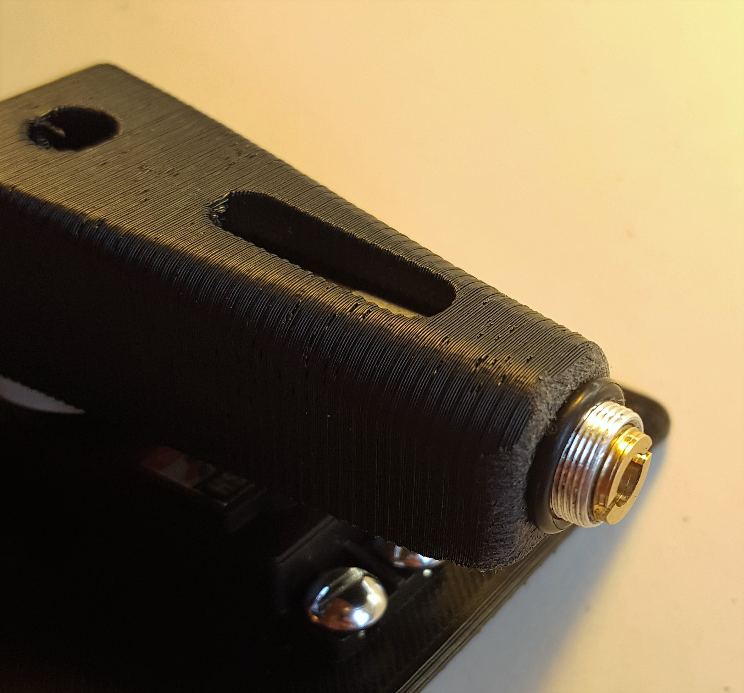
With the laser wired to the shield, push the laser through the hole in the top platform and into laser mount. Place the O-ring over exposed part of the laser to hold it in place. This can be a little finicky, so you can use hot glue to hold it in place.
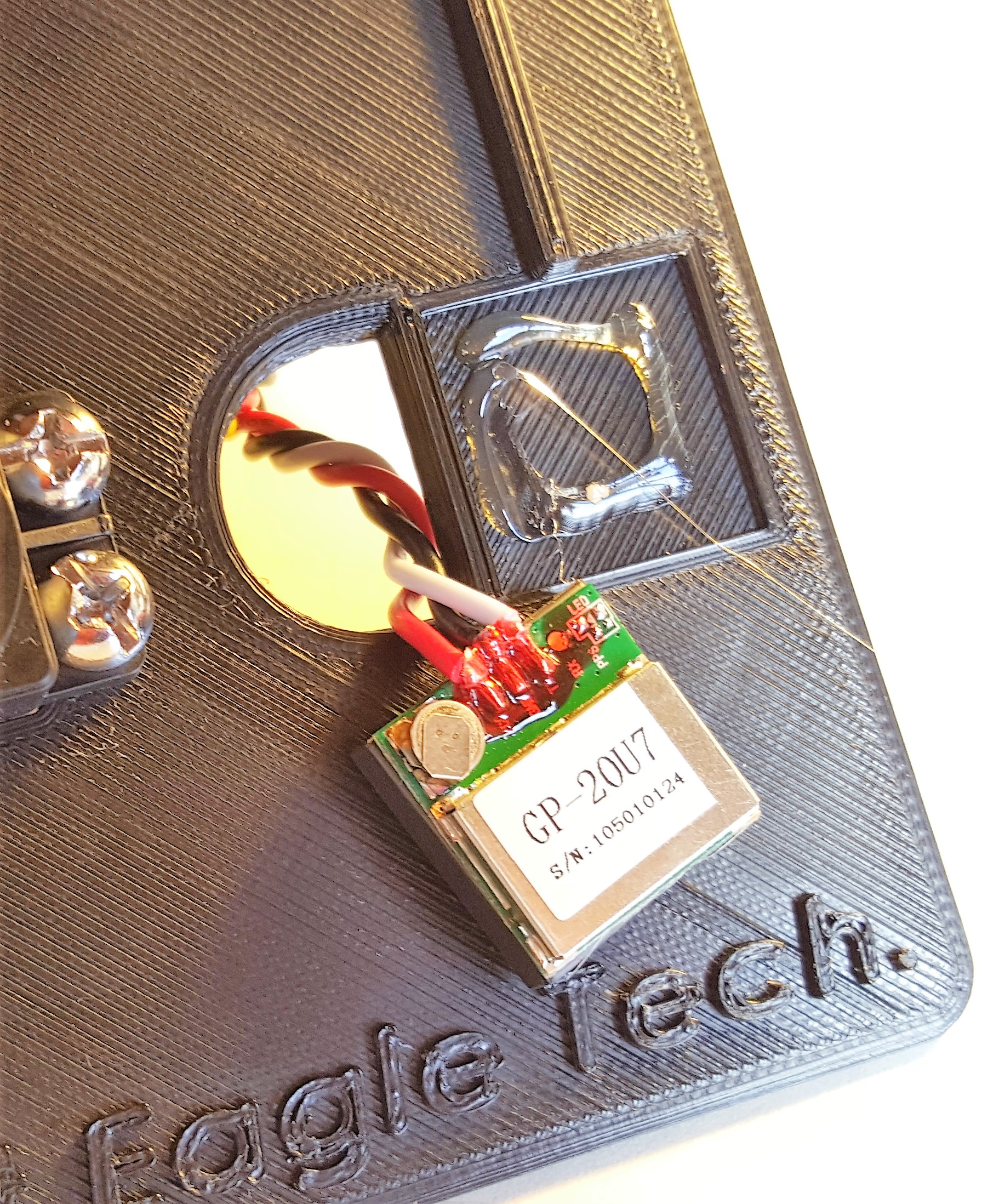
Attach the GPS receiver tot he indent made on top of the case. Again, make sure the wires stay inside the enclosure.
Attach the XBee Sheild to the RedBoard, if you haven't do so already, connect the wires, and you are good to go.
Target
Place the bare RedBoard in target case so that the USB port is facing the opening, and place 3 2-56 ¾” Machine screws into any three available holes. Use the corresponding nuts to secure them in place from the back.
Attach the 9V Battery holder using 3 1-72 ½” flathead screws, and secure them using the corresponding nuts on the back.
There is a cavity made for the GPS receiver sunk into the base. Use a glue gun or other adhesive method to hold it in place. Once everything is attached, place the XBee Shield back on the RedBoard and connect everything as shown in the Electronics Assembly section.

Code
Here is the basic code to get this system functioning. You will need to upload the files to their respective systems. There is a lot of room for you to play around with these to improve the speed or accuracy of the system. You will also need to include these libraries, which, depending on what version of the Arduino IDE you have installed, may already be included as a default library.
For help installing external Arduino libraries, visit this tutorial. Once all the libraies are installed, program each sketch from below on to the respective RedBoard.
Target Code
language:c
/*GPS Vector Pointer Target
   This sketch simiulates any system that has a GPS beacon and has the ability to
   broadcast this information for other systems to pick up. This could be a plane/drone
   a car/rover or even a solar panel on a space elevator climber. This recieves updating GPS
   coordinates and from an attached GPS reciever, parses the incoming NEMA data and
   send that information using an Xbee connection to the base station.
*/


/*We need to include a couple outside librarys. TinyGPS.h enables a set of tools to
   parse NEMA data into usable GPS info such as latitude and longitude. SoftwareSerial.h gives
   this sketch the ability to use standard DIO pins as serial ports to communicate between
   other microcontrollers. in this case we need one for reciving NEMA data and one
   to communicate using the Xbee. The standard UART on the redboard is reserved for programming
   and as a serial connection to the consol for Control and information purposes.
*/
#include <TinyGPS.h>
#include <SoftwareSerial.h>

//At this point we will define the pins used for serial communication, we
// do this so its easy to change them if needed.
#define gpsRXPIN 5
#define gpsTXPIN 4//this one is unused and doesnt have a conection
#define XbeeRXPIN 2//in this case we will also not use this pin
#define XbeeTXPIN 3

//Next we define the objects used in this sketch this includes two SoftwareSerial objects
//one for refering to the GPS connection and one for the Xbee connection. we also create an
//object that allows us to access the TinyGPS library
SoftwareSerial tGPS (gpsRXPIN, gpsTXPIN);
SoftwareSerial XBee (XbeeRXPIN, XbeeTXPIN); // RX, TX
TinyGPS gps;

//Global variables and functions are declared here, this allows them to be called anywhere
//within the code and is helpful for passing data out of functions. Dont get in the habit \
// of using these though because as your code gets longer its easy to lose track of where
//you are changing these variables and can lead to a headach when a problem arises.
float TargetLat;
float TargetLon;
int Status = 0;
//Function headers can be placed here so that functions can be placed below your setup
//and loop function for a more logical flow of information.
void SendGPSLocation(float Lat, float Lon, int Status);
void getGPS( float* lat, float* lon, int* Status);

void setup() {
  //This function is run before the your program begins to loop, here we define the status
  //of pins that are used for inputs and outputs
  pinMode(gpsRXPIN, INPUT);
  pinMode(XbeeTXPIN, OUTPUT);
  //Next communication begins between the three systems along for the baud rate for each
  //some of these can handle a larger baud rate but you need to make sure they match what
  //they are communicating with
  tGPS.begin(9600);
  Serial.begin(9600);
  XBee.begin(9600);
  while (!Serial) {}
  //a message is printed to the console showing that everything is initailized and
  //the program is now functioning
  Serial.println("Hello");

}

void loop()
//This
{
  // Recieves NEMA data from GPS reciever and Parses Latitude and longitude data
  //returns information using pointers including info on stagnant data

  //because only one Software serial port can be read at the same time we must tell
  //the redboard what to listen to. Here we tell it to listen to the tGPS serial object
  //then call the function that will recieve and parse the signal from the GPS reciver
  tGPS.listen();
  getGPS(&TargetLat, &TargetLon, &Status);
  //Print status to console to know if you are getting good data or not.
  //No Lock = 0, Old Data(>5 sec old) = 1, Good Data = 2
  Serial.println(Status);
  Serial.println(TargetLon);
  Serial.println(TargetLat);
  //we dont want to waste precious processing space or battery power by sending bad data
  //back to the base station so only when the Status variable = 2 for good data we will send
  //the information to the base station
  if (Status == 2)
    //if the data is up to data, send it to base station
  {
    //Switch Software serial port to the Xbee
    XBee.listen();
    //wait for it to become availible(might be unneccesary
    while (!XBee) {}
    //call the function that turns the info into a string and sends it to base station
    SendGPSLocation(TargetLat, TargetLon, Status);
    //wait for 2 seconds to ensure base station does not get overloaded
    delay(1000);
  }


}


void SendGPSLocation(float Lat, float Lon, int Status)
/* this sketch will send values from one modual to another(starting by sending values to XTCU)
  This will eventually send parsed GPS data from the target modual to the base station modual
*/
{
  // Convert GPS data from float into string
  String latData = String(Lat, 5);
  String lonData = String(Lon, 5);


  //Concatinate needed data into one string that begins with $ so the parser knows when data starts
  String GPSdata = "$";

  GPSdata += latData;
  GPSdata += ",";
  GPSdata += lonData;
  //Send Data as string "xx.yyyyy,-xxx,yyyyy" not able to handle changing signs
  //but since this is a demo project thats ok
  XBee.println(GPSdata);
  //Print GPS string to console for debugging
  Serial.println(GPSdata);

}


void getGPS( float* lat, float* lon, int* Status)
/*This function switches the softserial pin to the one used for GPS then recieves NEMA data from a GPS
  reciver which is passed into a TinyGPS Object and parsed using its internal functions for $GPRMC info. This function uses
  pointers to pass infomation to pass back to parent function which includes Latitude, longitude,( velocity,
  heading) and the status of the GPS signal.

  function call where variables can be nammed whatever they want as long as they have &:
  getGPS(&latitude, &longitude, &Status);
*/
{
  //Initilize pin to recieve NEMA (have to do it here because we need to switch between
  //software serial pins (if time permits interrupts could be used)
  //pinMode(gpsRXPIN, INPUT);
  // tGPS.begin(9600);
  //define local variables
  float flat;
  float flon;
  unsigned long fix_age;

  //look for serial data from GPS and loop untill the end of NEMA string
  while (tGPS.available())
  {
    //Serial.println("YO");
    int c = tGPS.read();
    if (gps.encode(c));
    {}
  }
  //(is this the correct order for this?^^)

  //Pulled parsed data from gps object
  gps.f_get_position(&flat, &flon, &fix_age);
  *lat = flat;
  *lon = flon;
  //  float falt = gps.f_altitude(); // +/- altitude in meters
  //  float fc = gps.f_course(); // course in degrees
  //  float fmps = gps.f_speed_mps(); // speed in m/sec

  // check if data is relavent
  if (fix_age == TinyGPS::GPS_INVALID_AGE)
    //No fix detected;
  {
    *Status = 0;
  }

  else if (fix_age > 5000)
    //Warning: possible stale data!;
  {
    *Status = 1;
  }

  else
    //Data is current;
  {
    *Status = 2;
  }

}
Base Code
language:c
/* GPS Vector Pointer Base Station
  By: Dustin Larsen
  Abstract Eagle Technologies
  Date: March 20th, 2016
  (Beerware license): This code is public domain but you enjoy the project and we meet someday buy me a beer.

    This sketch controls the Base station functionality and includes the ability to
    recieve GPS coordinates from the target object and compare it to the GPS coordinates
    of the Base station GPS Location. The location of the base station will be calculated
    using a function that increases its accuracy over time by storing all previous values.
    The direction vector between the base station and the target object will then be calculated
    and a servo will be commanded to point a LASER in the direction of the target object.
*/

// gives the ability to use standard DIO pins as serial ports to communicate between other microcontrollers.
#include <SoftwareSerial.h>
//enables a set of tools to parse NEMA data into usable GPS info such as latitude and longitude
#include <TinyGPS.h>
//Enables the use of the servo Library to easily control an analog servo
#include <Servo.h>;


//pins are defined here so they can be easily referenced and changed if needed
#define gpsRXPIN 5
#define gpsTXPIN 4
#define XbeeRXPIN 2
#define XbeeTXPIN 3
#define ServoPIN 9


//define the objects for the included librarys used in this sketch
SoftwareSerial bGPS (gpsRXPIN, gpsTXPIN);
SoftwareSerial XBee (XbeeRXPIN, XbeeTXPIN);
TinyGPS gps;
Servo servo1;


//Global variables are declared here, this allows them to be called anywhere
//within the code and is helpful for passing data out of functions.
float baseLat = 0;
float baseLon = 0;
float baseavgLat;
float baseavgLon;
float targetLat = 0;
float targetLon = 0;
int Status = 0;

//Function headers introduced so functions can be called from anywhere in your sketch for a more logical flow of information.
void getGPS( float* lat, float* lon, int* Status);
void RecieveGPSLocation(float* latData, float* lonData);
void ServoPointCommand(double baseLat, double baseLon, double targetLat, double targetLon);

void setup() {


 //define the status of pins that are used for inputs and outputs
  pinMode(XbeeRXPIN, INPUT);
  pinMode(gpsRXPIN, INPUT);

 //Begin communication with the XBee, the GPS reciver and the Serial console
  XBee.begin(9600);
  bGPS.begin(9600);
  Serial.begin(9600);
  //while (!Serial) {}
  //a message is printed to the console showing that everything is initailized and
  //the program is now functioning
  Serial.println("goodnight moon!");
 }

void loop() {

  //Software serial can only look at one input at a time so we must tell it what to listen to
  //here the sketch switches software serial to Xbee
  XBee.listen();
  //wait for buffer to fill
  delay(2);
  //recieve and parse target GPS location
  RecieveGPSLocation(&targetLat, &targetLon);


  //Switches software serial to GPS
  bGPS.listen();
  //wait for buffer to fill
  delay(2);
  //loops through getGPS function so that it does not stop listening before
  //current data can be gathered
  int  count = 15;
  while ( count > 0) {
    getGPS( &baseLat, &baseLon, &Status);
    count-- ;
    //if data up to date break out of the loop and reset the count
    if (Status == 2)
    {
      bothGPSknown();
      count = 0;
      break;//redundant?
    }
  }
}

void bothGPSknown()
{
  //once both sets of coordinates are known stop listening to GPS and attach
  //the servo so that it does not recieve noise from GPS reciver(It will twich randomly if you dont do this)
  XBee.listen();
  servo1.attach(ServoPIN);
  //Average the the current base data with the existing, this will increase the accuracy over time since
  //the base hardware will not move even if the GPS data jumps around
  baseavgLat = (baseLat + baseavgLat) / 2;
  baseavgLon = (baseLon + baseavgLon) / 2;

//Print out info to Serial Console
  Serial.print("Base Latitude:");
  Serial.println(baseavgLat, 5);
  Serial.print("Base Longitude:");
  Serial.println(baseavgLon, 5);
  Serial.print("Target Latitude:");
  Serial.println(targetLat, 5);
  Serial.print("Target Longitude:");
  Serial.println(targetLon, 5);
  //passes this data GPS data to control servo
  ServoPointCommand(baseavgLat, baseavgLon, targetLat, targetLon);
  //wait after pointing angle commanded
  delay(1000);
  //Detach servo to prevent jittering while not in use
  servo1.detach();
  //Define status of data as stale
  Status = 1;
}

void RecieveGPSLocation(float* latData, float* lonData)
/*
   This function looks for a current GPS value to be recieved from target which then reads nthe
   compound string and places latitude and longitude data into their respective strings
   then converts those strings to float to pass variables back to main loop using pointers
*/
{
  //declares and clears variables used in this function
  String GPSdata = "";
  char inChar;
  String A = "";

  //reads buffer till string identifier is seen
  while ( inChar != '$')
  {
    inChar = XBee.read();
  }
  //once data string is identified loop till "\n" is seen which identifies the end of the data

  while ( inChar != '\n' ) {
    //wait for buffer to fill
    delay(1);
    //read next character
    inChar = XBee.read();
    //concatinate into GPSdata string
    GPSdata += inChar;
  }


  //Parse Latitude data from string and send it back to main loop
  A = GPSdata.substring(0,  9);
  *latData = A.toFloat();
  //Clear string A
  A = "";
  //Parse Longitude data from string and send it back to main loop
  A = GPSdata.substring(9);
  *lonData = A.toFloat();

}

void getGPS( float* lat, float* lon, int* Status)
/*This function switches the softwareserial pin to the one used for the GPS reciver then recieves the NEMA data
  which is passed into a TinyGPS Object and parsed using its internal functions for $GPRMC info. This function uses
  pointers to pass infomation to pass back to parent function which includes Latitude, longitude,and Status of the GPS signal.

  function call where variables can be nammed whatever they want as long as they have &:
  getGPS(&latitude, &longitude, &Status);
*/
{
  //define local variables
  float flat;
  float flon;
  unsigned long fix_age;

  //look for serial data from GPS and loop untill the end of NEMA string
  while (bGPS.available())
  {
    int c = bGPS.read();
    if (gps.encode(c));
    {
    }
    delay(2); //this delay is a fine lie, may have problems later
  }

  // Use tinyGPS library to parse information
  gps.f_get_position(&flat, &flon, &fix_age);
  *lat = flat;
  *lon = flon;

  // check if data is relavent and print update to serial port
  if (fix_age == TinyGPS::GPS_INVALID_AGE)
    //No fix detected;
  {
    *Status = 0;
    //delay(10);
    //Serial.println("");
    Serial.println("no GPS data recieved from base");//doesnt work when I take out print functions
  }

  else if (fix_age > 5000)
    //Warning: possible stale data!;
  {
    *Status = 1;
    // delay(10);
    Serial.println("Stale GPS data recieved from base");
  }

  else
    //Data is current;
  {
    *Status = 2;
    //delay(10);
    //Serial.println("");
    Serial.println("GPS data recieved from base");
  }

}

void ServoPointCommand(float baseLat, float baseLon, float targetLat, float targetLon)
/* THis function will take the cordinates of the base station and the target object
    then calculate the angle between then using the inverse tangent function.
*/
{
  //Define Local variables
  float latDiff, lonDiff, theta;
  double servoPosition;

  //Calculate difference
  latDiff = (targetLat - baseLat);
  lonDiff = (targetLon - baseLon);
  //Calculate angle
  theta =   atan2 (latDiff, lonDiff);
  theta = theta * 180 / 3.145;

  //Print result to console
  Serial.println("latDiff");
  Serial.println(latDiff);
  Serial.println("lonDiff");
  Serial.println(lonDiff);
  Serial.println("theta");
  Serial.println(theta);

  //Map the calculated angle into a value the servo will understand
  servoPosition = map(theta, -180, 0, 0, 180);
  servoPosition = constrain(servoPosition, 0, 180);
  servo1.write(servoPosition);

}
Operation
To ensure the system aligns with the earth's frame of reference and is in the correct orientation, use the compass to line the arrow on the Base Station top with true North. Once powered up, both systems will sit idle as they acquire a satellite lock. Once both have established a lock, which may take up to a minute, the servo will point to where it interprets the target object is. This will update continuously to point at the most recent location of the target object. If the angle is substantially off or the servo is maxed out in one direction you might need to make sure the whole system is pointing in the right direction since it is limited in which direction it works.
Resources and Going Further
Ready to get hands-on with GPS?
We've got a page just for you! We'll walk you through the basics of how GPS works, the hardware needed, and project tutorials to get you started.
Thanks for Reading!
The code for this project can be found on the GitHub Repository.
For more GPS fun, check out these other SparkFun tutorials: