GPS-RTK2 Hookup Guide
 Nate
Nate 
Setting the ZED-F9P as a Correction Source
If you’re located further than 20km from a correction station you can create your own station using the ZED-F9P. u-blox provides a setup guide within the ZED-F9P Integration Manual showing the various settings needed via u-Center. We’ll be covering how to setup the ZED-F9P using I2C commands only. This will enable a headless (computerless) configuration of a base station that outputs RTCM correction data.
Before getting started we recommend you configure the module using u-center. Checkout our tutorial on using U-Center then read section 3.5.8 Base Station Configuration of the u-blox Integration Manual for getting the ZED-F9P configured for RTK using u-center. Once you’ve been successful controlling the module in the comfort of your lab using u-center, then consider heading outdoors.
For this exercise we’ll be using the following parts:
- 1x SparkFun GPS-RTK2 Board or RTK-SMA Board
- 1x U.FL to SMA Cable for the RTK2
- 1x SparkFun BlackBoard makes I2C easy
- 1x USB C 2.0 Cable if you need one
- 1x Two Qwiic Cables
- 1x 20x4 SerLCD with Qwiic Adapter soldered on
- 1x Antenna L1/L2 GNSS 3-5V Magnetic Mount
- 1x GPS Antenna Ground Plate
- 1x 20+ft SMA extension can be handy when first experimenting with base stations so you can sit indoors with a laptop and analyze the output of the GPS-RTK
- 1x A standard camera tripod
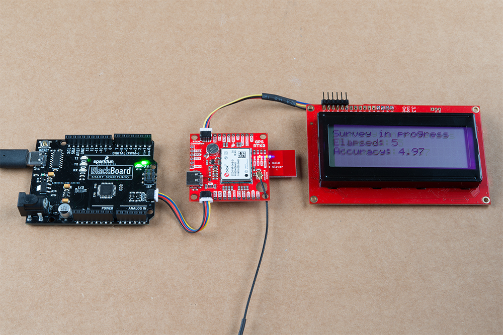
The ZED-F9P can be configured using Serial, SPI, or I2C. We’re fans of the daisy chain-ability of I2C so we’ll be focusing on the Qwiic system. For this exercise we’ll be connecting the an LCD and GPS-RTK2 to a BlackBoard using two Qwiic cables. You can also use the RTK-SMA as an alternative.
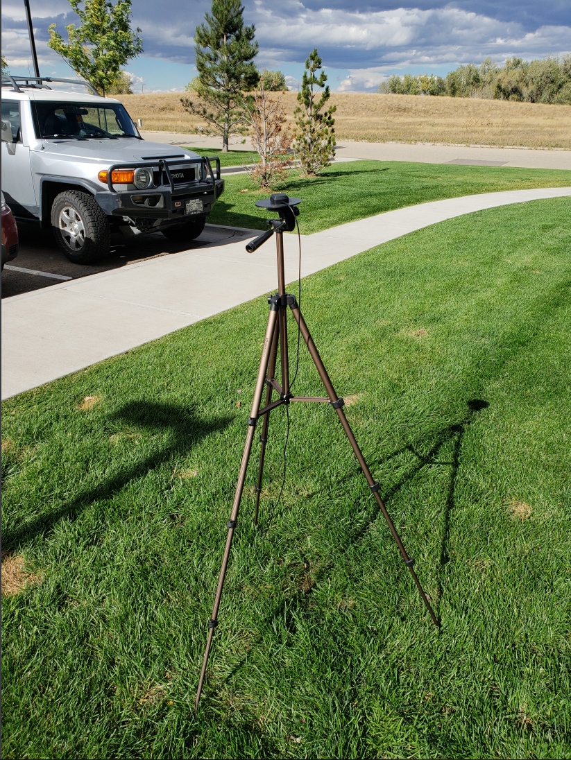
For the antenna, you’ll need a clear view of the sky. The better your antenna position the better your accuracy and performance of the system. We designed the GPS Antenna Ground Plate to make this setup easy. The plate has a ¼” threaded hole that threads directly onto a camera tripod. The plate thickness was chosen to be thick enough so that the threaded screw is flush with the plate so it won’t interfere with the antenna. Not sure why we’re using a ground plate? Read the u-blox white paper on using low-cost GNSS antennas with RTK. Mount your magnetic mount antenna and run the SMA cable to the U.FL to SMA cable to the GPS-RTK2 board. If you have the RTK-SMA, you just need to run the SMA cable to the board's connector.
There are only three steps to initiating a base station:
- Enable Survey-In mode for 1 minute (60 seconds)
- Enable RTCM output messages
- Being Transmitting the RTCM packets over the backhaul of choice
Be sure to grab the SparkFun Arduino Library for u-blox. You can easily install this via the library manager by searching ‘SparkFun u-blox GNSS’. Once installed click on File -> Examples -> SparkFun_u-blox_GNSS_Arduino_Library.
The ZED-F9P subfolder houses a handful of sketches specific to its setup. Example3 of the library demonstrates how to send the various commands to the ZED-F9P to enable Survey-In mode. Let’s discuss the important bits of code.
language:c
response = myGNSS.enableSurveyMode(60, 5.000); //Enable Survey in, 60 seconds, 5.0m
The library is capable of sending UBX binary commands with all necessary headers, packet length, and CRC bytes over I2C. The enableSurveyMode(minimumTime, minimumRadius) command does all the hard work to tell the module to go into survey mode. The module will begin to record lock data and calculate a 3D standard deviation. The survey-in process ends when both the minimum time and minimum radius are achieved. u-blox recommends 60 seconds and a radius of 5m. With a clear view of the sky, with a low cost L1/L2 GNSS antenna mounted to a ground plate we’ve seen the survey complete at 61 seconds with a radius of around 1.5m.
language:c
response &= myGNSS.enableRTCMmessage(UBX_RTCM_1005, COM_PORT_I2C, 1); //Enable message 1005 to output through I2C port, message every second
response &= myGNSS.enableRTCMmessage(UBX_RTCM_1074, COM_PORT_I2C, 1);
response &= myGNSS.enableRTCMmessage(UBX_RTCM_1084, COM_PORT_I2C, 1);
response &= myGNSS.enableRTCMmessage(UBX_RTCM_1094, COM_PORT_I2C, 1);
response &= myGNSS.enableRTCMmessage(UBX_RTCM_1124, COM_PORT_I2C, 1);
response &= myGNSS.enableRTCMmessage(UBX_RTCM_1230, COM_PORT_I2C, 10); //Enable message every 10 seconds
These six lines enable the six RTCM output messages needed for a second ZED-F9P to receive correction data. Once these sentences have been enabled (and assuming a survey process is complete) the ZED-F9P base module will begin outputting RTCM data every second after the NMEA sentences (the RTCM_1230 sentence will be output once every 10 seconds). You can view an example of what this output looks like here.
The size of the RTCM correction data varies but in general it is approximately 2000 bytes every second (~2500 bytes every 10th second when 1230 is transmitted).
language:c
//This function gets called from the SparkFun u-blox GNSS Arduino Library.
//As each RTCM byte comes in you can specify what to do with it
//Useful for passing the RTCM correction data to a radio, Ntrip broadcaster, etc.
void SFE_UBLOX_GNSS::processRTCM(uint8_t incoming)
{
  //Let's just pretty-print the HEX values for now
  if (myGNSS.rtcmFrameCounter % 16 == 0) Serial.println();
  Serial.print(" ");
  if (incoming < 0x10) Serial.print("0");
  Serial.print(incoming, HEX);
}
If you have a ‘rover’ in the field in need of correction data you’ll need to get the RTCM bytes to the rover. The SparkFun u-blox library automatically detects the difference between NMEA sentences and RTCM data. The processRTCM() function allows you to ‘pipe’ just the RTCM correction data to the channel of your choice. Once the base station has completed the survey and has the RTCM messages enabled, your custom processRTCM() function can pass each byte to any number of channels:
- A wireless system such as LoRa or Cellular
- Posting the bytes over the internet using WiFi or wired ethernet over an Ntrip caster
- Over a wired solution such as RS485
The power of the processRTCM() function is that it doesn’t care; it presents the user with the incoming byte and is agnostic about the back channel.
What about configuring the rover? u-blox designed the ZED-F9P to automatically go into RTK mode once RTCM data is detected on any of the ports. Simply push the RTCM bytes from your back channel into one of the ports (UART, SPI, I2C) on the rover's ZED-F9P and the location accuracy will go from meters to centimeters. The rover's NMEA messages will contain the improved Lat/Long data and you'll know where you are with mind-bending accuracy. It’s a lot of fun to watch!