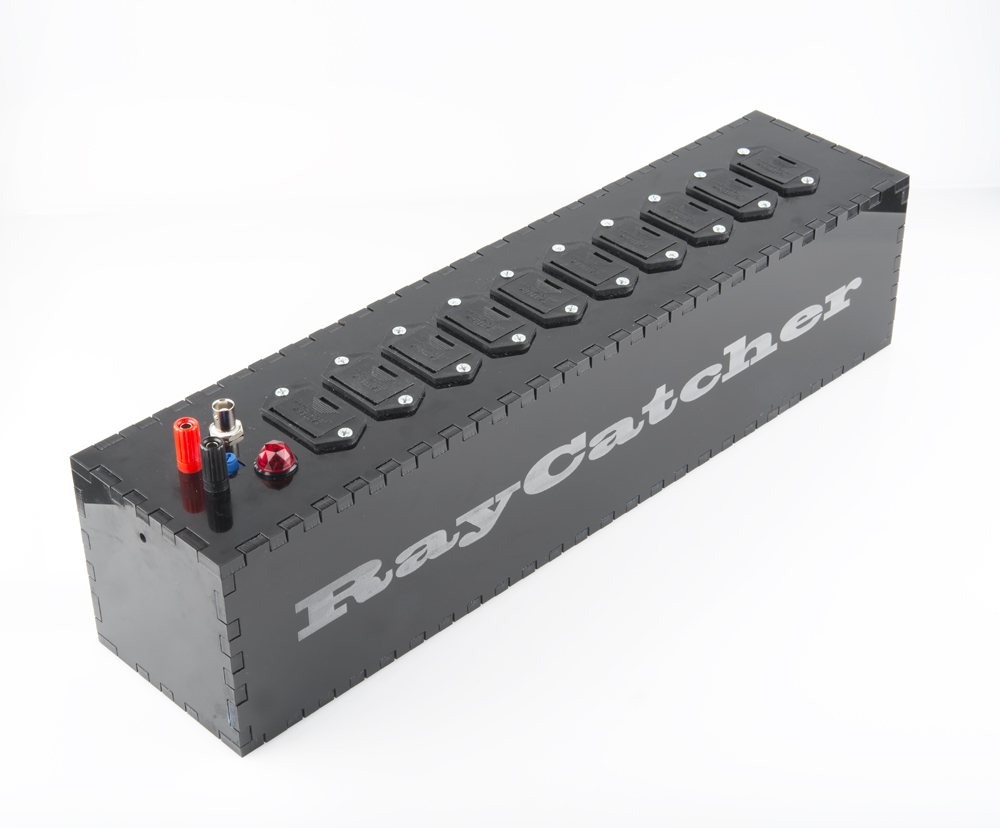
Hackers in Residence - Cosmic Ray Detector
Catching Some Rays
This project seeks to create an inexpensive cosmic ray detector capable of sensing rays greater than 1 GeV in energy. These can be used either as part of a timing synchronization solution, or as part of a large, distributed cosmic ray telescope.
WARNING!
This project deals with high voltage. Make certain to use appropriate precautions. Do not cut any wires while all batteries are connected; remove and replace batteries while wearing nitrile gloves if using standard battery clips. Drawer-type battery holders, such as the ones used in this project, do not necessitate the use of gloves.
Required Materials
Along with the parts listed above, you will also need a neon bulb.
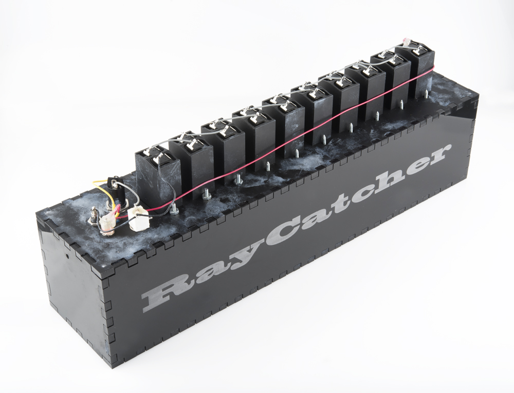
Note that there are two options for battery holders. The less expensive one certainly works, but the more expensive one is safer, as it allows separation of the battery mechanically with no shock risk.
Tools Needed
- Soldering Iron
- Solder
- Wire Cutter
- Wire Stripper
- Tweezers
- Hot Glue Gun
- Hot Glue
Suggested Reading
Circuit
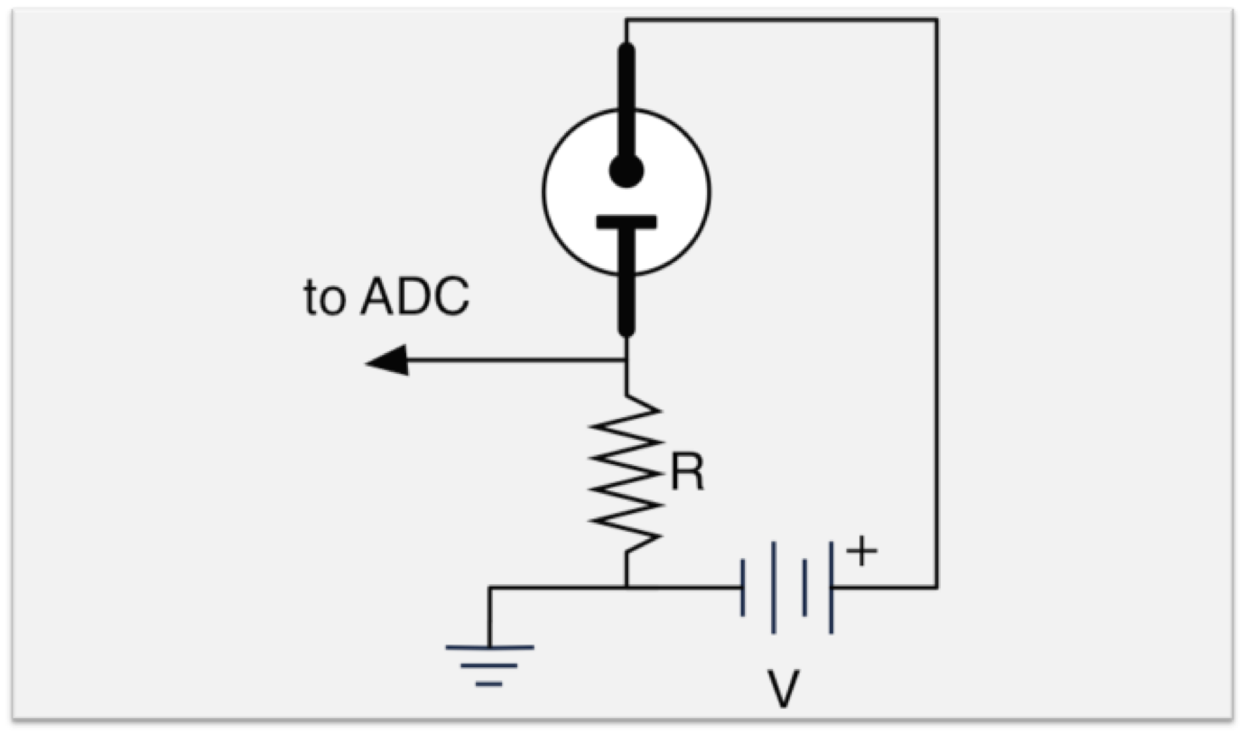
In this circuit diagram, R is the sense resistor, usually about 1 kΩ, and V is the bias voltage. The bias voltage should be less than the turn-on voltage (usually either 95 or 65 VDC depending on the type of bulb being used), but should be high enough that a cosmic ray can trigger the circuit, causing a current to flow through the resistor. This is usually about 80-94 VDC, and can be supplied by a bank of 9-volt batteries, or a DC-DC converter that has a sufficiently large capacitor across it to absorb all transients.

Assembly
Begin by clipping the end connectors off of the 9-volt battery holders. Strip about 5-10 mm of insulation off of the end of each wire.
Twist the red (+) wire of one connector and the black (-) wire of another together. Hold the joint in a pair of tweezers while soldering it together. Repeat until all of the 9-volt connectors have been soldered in this fashion into a line.
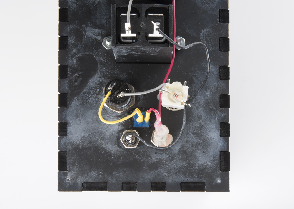
Solder the 1 kΩ resistor across the two wires on the female BNC connector. Glue over the 1 kΩ resistor on the bottom of the BNC connector. Connect the ground (outer) wire from the BNC connector to the loose black (-) wire on the 9-volt connectors, and solder it.
Solder the signal (inner) wire from the BNC connector to one of the two leads of the Neon bulb. Repeat for the other lead of the Neon bulb to one of the two outer pins of the 10 kΩ trimpot. Cut the other outer pin of the trimpot.
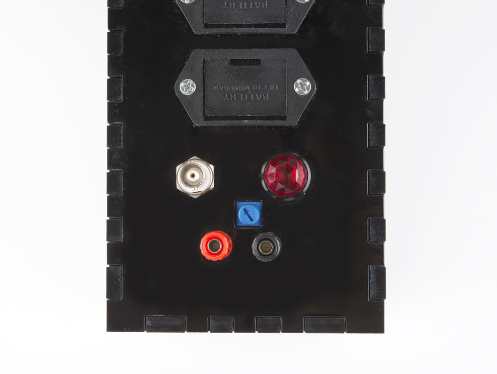
Attach the middle pin of the trimpot to the loose red (+) wire on the 9-volt connectors. Then solder the black (ground) lead from the battery connectors to the bottom of the black binding post and solder the red (+V) lead from the battery connectors to the red binding post. Put small globs of hot glue on each and every soldered connection. Turn the trimpot all the way in the direction that is towards the remaining outside pin.
Last, connect the batteries to their connectors.
Testing
Tools Needed
- Oscilloscope, Arduino, Audio Recorder, or Other Output/Logging Device
- Smoke Detector or Propane Lamp Mantle as Radiation Source
- BNC-to-BNC or BNC-to-Dual Alligator Cable
- Nitrile Gloves
Procedure
- Connect the detector to the output or logging device using one of the above cables.
- Allow for the unit to sit for a few hours with data being logged at as high of a sampling rate as possible.
- Put on gloves.
- Power down the detector by removing one battery.
- Re-power the detector by reconnecting the battery.
- Place smoke detector sensor or propane lamp mantle right over the neon bulb, and allow it to sit there for a few minutes.
- Remove the radiation source, and remove gloves using this method.
- Check the data: there should be some spikes in the signal several samples wide during the first few hours, while there should be no additional spikes during the time that the detector was exposed to the radiation source.
Troubleshooting
- If there is a greater rate of spikes in the region of the data after the radiation source is introduced, turn the trimpot a few degrees and try again until the rate is as low as can be.
- If at any point the neon bulb turns on, remove one battery to turn the detector off, rotate the trimpot a few degrees, and reattach the battery. If it comes back on, repeat this procedure.