HMC6343 3-axis Compass Hookup Guide
 JordanDee
Hardware Overview
The Breakout Board for the HMC6343 breaks out the all the pins you'll need to send commands and collect data from the electronic compass.
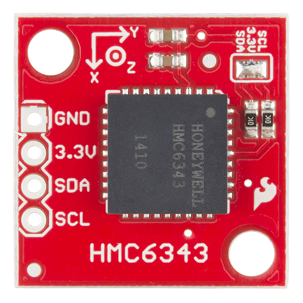
As you can see, the breakout has only four pins broken out. Two are for power, 3.3V and GND. Two are for I2C communication, SCL (clock) and SDA (data).
Voltage Supply Requirements
The big alert here is that the HMC6343 has an input voltage range of 2.7V - 3.6V -- that range applies to both the power supply and the I2C lines. You can use a 5V or 3.3V micro with this sensor as long as you power the board with 3.3V and use a logic level converter for the I2C lines if you're using a 5V micro like the Arduino Uno.
Fortunately, you don't need a lot of power to make the HMC6343 work. In the normal operating mode, the IC typically draws about 4.5mA. It draws even less current in standby (1mA) or sleep (10µA) modes.
Extra Hardware Notes
The HMC6343 can measure and compute a heading direction every 200ms (5Hz). Being able to easily acquire a tilt compensated heading direction accurate within a couple degrees without having your microprocessor spend a lot of time on computation is the highlight of this IC. However, you can read raw magnetometer and accelerometer values if needed.
The HMC6343 has two mounting holes to allow for a secure physical connection to your project. You certainly don't want the board moving/twisting around independently of your system if you're depending on it to give you a sense of direction.
Also, there is a solder jumper on the top of the board that is closed by default so that the I2C lines have 10KΩ pull-up resistors. If you want to use a different values for your I2C pull-ups, you can disconnect these default resistors by removing the solder from the jumper.