How to Use a Breadboard
 M-Short,
  Joel_E_B
Building Your First Breadboard Circuit
Now that we're familiar with the internals of a breadboard and how to provide power to them, what do we do with them? We are going to start with a simple circuit.
What You’ll Need
Here is a parts list to follow along with this circuit. If you have other electronic bits and pieces, feel free to use them and change the circuit up. Remember, there is often more ways than one to build any given circuit. Some even have dozens of different ways that you can build them.
This wish list assumes you don't have any parts/tools and is generous with quantities etc. For example, you only need one LED for this project, but the pack listed has 20 LEDs in it. The same is true with the hook-up wire. You don't need that much (or all those colors), but if you keep playing with circuits, it could come in handy. If you don't want the higher quantities check the bottom of the product pages in the section called "Related Products" and you should be able to find smaller quantities. Also, the breadboard power supply doesn't have headers, if you know how to solder and have the tools, solder the headers on yourself. If not, solderless headers have been included in the wishlist as well.
Build the Circuit
Here is a small circuit on a breadboard. The red board you see is the Breadboard Power Supply Stick with headers soldered to the PCB. The breadboard power supply stick regulates voltage from a 9V wall wart to either 5V or 3.3V to the power rails.
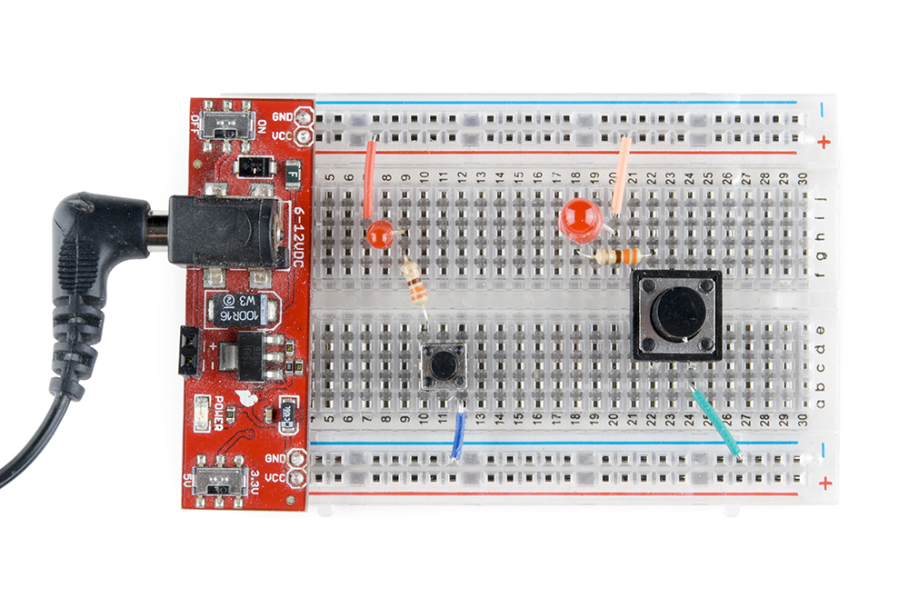
The circuit goes as follows:
There is a wire connecting the VCC power rail to the positive, anode leg of an LED.
The negative, cathode leg of the LED is connected to a 330Ω resistor.
The resistor is then connected to a button.
When the button is pushed, it connects the circuit to ground completing the circuit and turning on the LED.
Circuit Schematics
We cover how to read a schematic in another tutorial. However, it is a very important part of building circuits, so it will be covered here in short.
Schematics are universal pictograms that allow people all over the world to understand and build electronics. Every electronic component has a very unique schematic symbol. These symbols are then assembled into circuits using a variety of programs. You could also draw them out by hand. If you want to dive deeper in the world of electronics and circuit building, learning to read schematics is a very important step in doing so.
Here we have a schematic for the above circuit. Power (assuming the switch is flipped to the 5V side) is represented by the arrow at the top. It then goes to the LED (the triangle and line with arrows emitting out of it). The LED is then connected to the resistor (the squiggly line). That is connected to the button (the latch-looking symbol). Last the button is connect to ground (the horizontal line at the bottom).
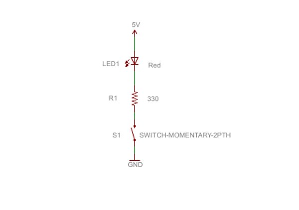
This may seem like a funny way to draw a circuit, but it is a fundamental process that has been around for decades. Schematics allow people from different nationalities and languages to build and collaborate on circuits designed by anyone. As mentioned, you can build a circuit in many different ways, but, as this schematic shows, there are certain connections that must be made. Diverging from this schematic will give you an entirely different circuit.
Practice Makes Perfect
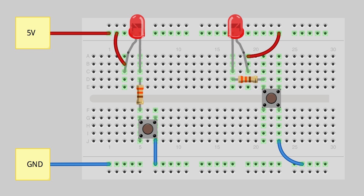
The last bit of knowledge to leave you with is that there are tons of resources and programs you can use to build circuits without having to actually use your breadboard. One very common program used by SparkFun is Fritzing. Fritzing is a free program that allows you to build your own circuits on a virtual breadboard. It also provides schematic views for all the circuits you build. Here we can see the same circuits as above built using Fritzing.
There are many other programs like Fritzing. Some are free, and some are paid. Some will even allow you to build a circuit and test its functionality through simulations. Go explore the internet, and find the tools that work best for you.