How to Use an Oscilloscope
 jimblom
Anatomy of An O-Scope
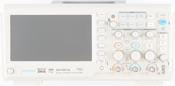
While no scopes are created exactly equal, they should all share a few similarities that make them function similarly. On this page we'll discuss a few of the more common systems of an oscilloscope: the display, horizontal, vertical, trigger, and inputs.
The Display
An oscilloscope isn’t any good unless it can display the information you’re trying to test, which makes the display one of the more important sections on the scope.
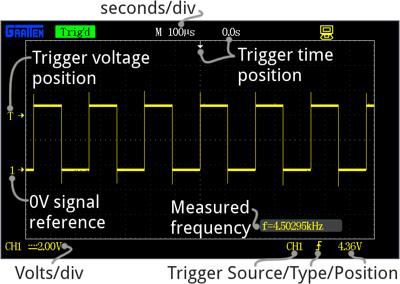
Every oscilloscope display should be criss-crossed with horizontal and vertical lines called divisions. The scale of those divisions are modified with the horizontal and vertical systems. The vertical system is measured in “volts per division” and the horizontal is “seconds per division”. Generally, scopes will feature around 8-10 vertical (voltage) divisions, and 10-14 horizontal (seconds) divisions.
Older scopes (especially those of the analog variety) usually feature a simple, monochrome display, though the intensity of the wave may vary. More modern scopes feature multicolor LCD screens, which are a great help in showing more than one waveform at a time.
Many scope displays are situated next to a set of about five buttons -- either to the side or below the display. These buttons can be used to navigate menus and control settings of the scope.
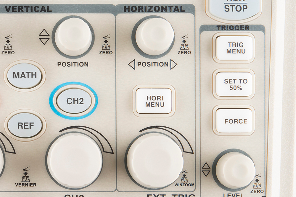
Vertical System
The vertical section of the scope controls the voltage scale on the display. There are traditionally two knobs in this section, which allow you to individually control the vertical position and volts/div.
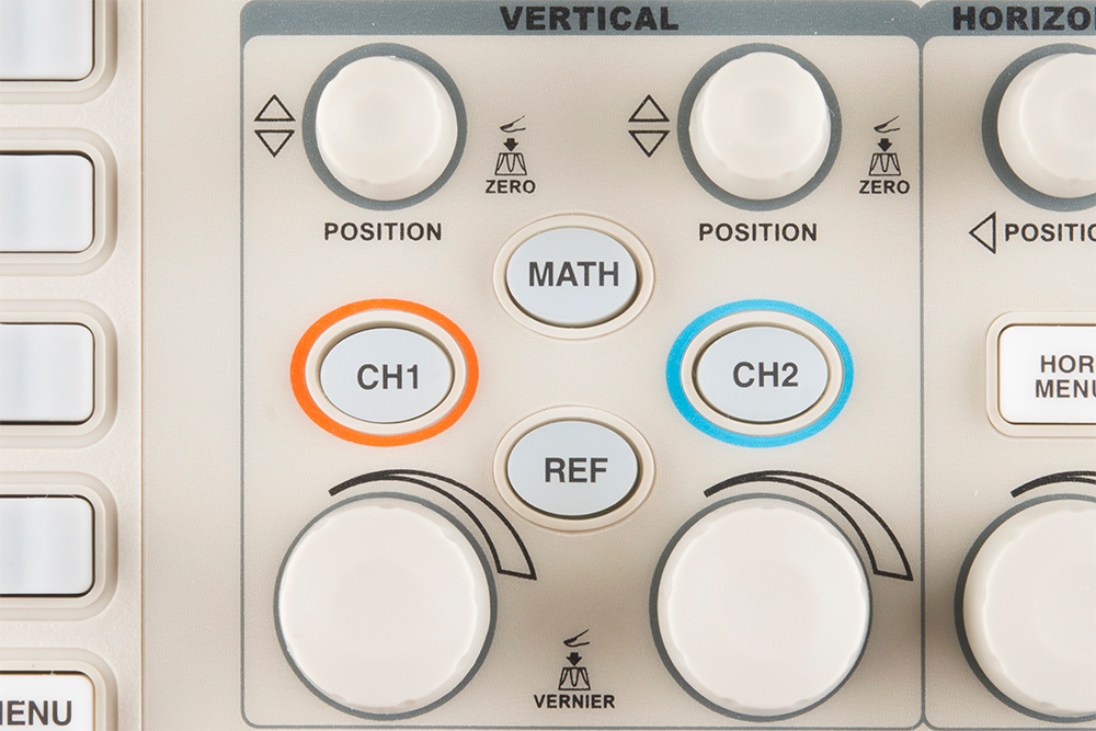
The more critical volts per division knob allows you to set the vertical scale on the screen. Rotating the knob clockwise will decrease the scale, and counter-clockwise will increase. A smaller scale – fewer volts per division on the screen – means you’re more “zoomed in” to the waveform.
The display on the GA1102, for example, has 8 vertical divisions, and the volts/div knob can select a scale between 2mV/div and 5V/div. So, zoomed all the way in to 2mV/div, the display can show waveform that is 16mV from top to bottom. Fully “zoomed out”, the scope can show a waveform ranging over 40V. (The probe, as we’ll discuss below, can further increase this range.)
The position knob controls the vertical offset of the waveform on the screen. Rotate the knob clockwise, and the wave will move down, counter-clockwise will move it up the display. You can use the position knob to offset part of a waveform off the screen.
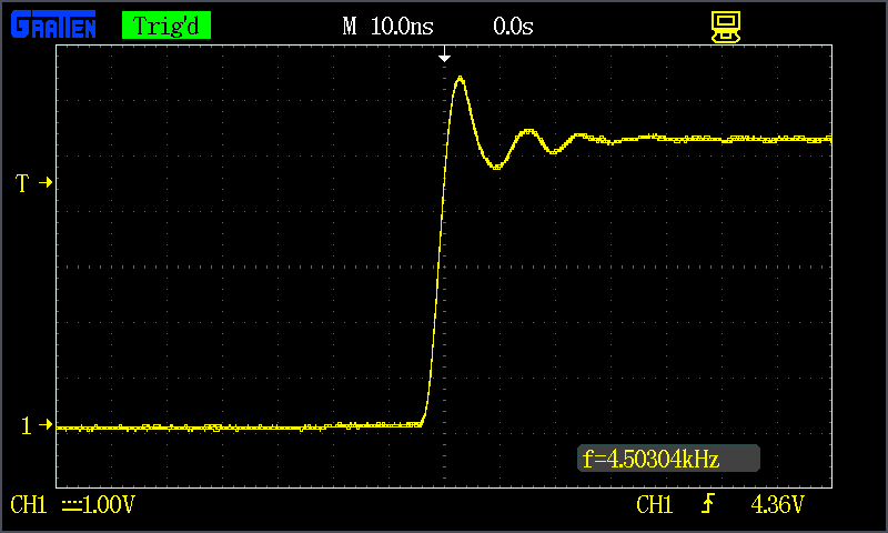
Using both the position and volts/div knobs in conjunction, you can zoom in on just a tiny part of the waveform that you care about the most. If you had a 5V square wave, but only cared about how much it was ringing on the edges, you could zoom in on the rising edge using both knobs.
Horizontal System
The horizontal section of the scope controls the time scale on the screen. Like the vertical system, the horizontal control gives you two knobs: position and seconds/div.
The seconds per division (s/div) knob rotates to increase or decrease the horizontal scale. If you rotate the s/div knob clockwise, the number of seconds each division represents will decrease – you’ll be “zooming in” on the time scale. Rotate counter-clockwise to increase the time scale, and show a longer amount of time on the screen.
Using the GA1102 as an example again, the display has 14 horizontal divisions, and can show anywhere between 2nS and 50s per division. So zoomed all the way in on the horizontal scale, the scope can show 28nS of a waveform, and zoomed way out it can show a signal as it changes over 700 seconds.
The position knob can move your waveform to the right or left of the display, adjusting the horizontal offset.
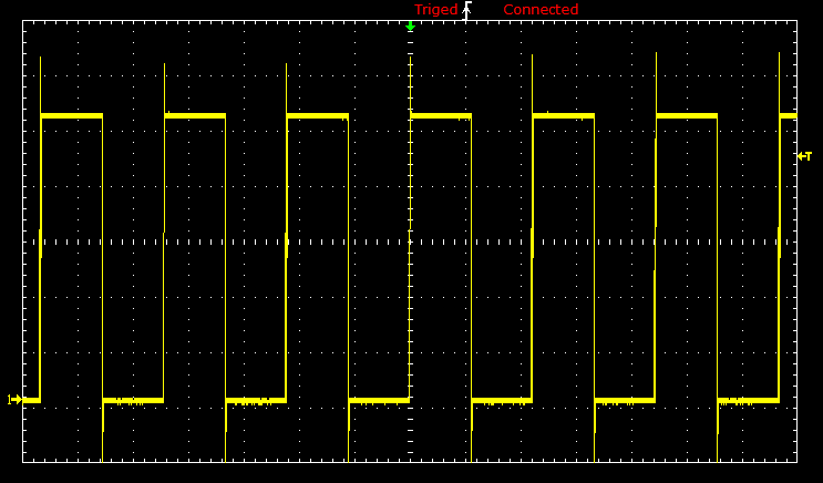
Using the horizontal system, you can adjust how many periods of a waveform you want to see. You can zoom out, and show multiple peaks and troughs of a signal:
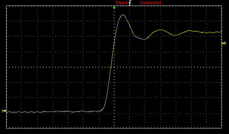
Or you can zoom way in, and use the position knob to show just a tiny part of a wave:
Trigger System
The trigger section is devoted to stabilizing and focusing the oscilloscope. The trigger tells the scope what parts of the signal to “trigger” on and start measuring. If your waveform is periodic, the trigger can be manipulated to keep the display static and unflinching. A poorly triggered wave will produce seizure-inducing sweeping waves like this:
The trigger section of a scope is usually comprised of a level knob and a set of buttons to select the source and type of the trigger. The level knob can be twisted to set a trigger to a specific voltage point.
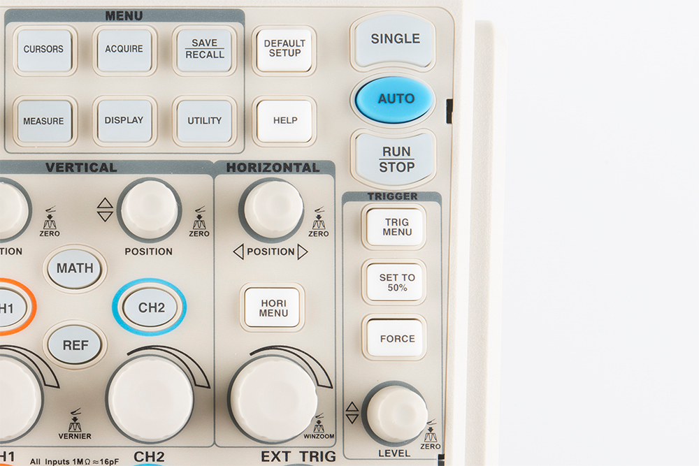
A series of buttons and screen menus make up the rest of the trigger system. Their main purpose is to select the trigger source and mode. There are a variety of trigger types, which manipulate how the trigger is activated:
- An edge trigger is the most basic form of the trigger. It will key the oscilloscope to start measuring when the signal voltage passes a certain level. An edge trigger can be set to catch on a rising or falling edge (or both).
- A pulse trigger tells the scope to key in on a specified “pulse” of voltage. You can specify the duration and direction of the pulse. For example, it can be a tiny blip of 0V -> 5V -> 0V, or it can be a seconds-long dip from 5V to 0V, back to 5V.
- A slope trigger can be set to trigger the scope on a positive or negative slope over a specified amount of time.
- More complicated triggers exist to focus on standardized waveforms that carry video data, like NTSC or PAL. These waves use a unique synchronizing pattern at the beginning of every frame.
You can also usually select a triggering mode, which, in effect, tells the scope how strongly you feel about your trigger. In automatic trigger mode, the scope can attempt to draw your waveform even if it doesn’t trigger. Normal mode will only draw your wave if it sees the specified trigger. And single mode looks for your specified trigger, when it sees it it will draw your wave then stop.
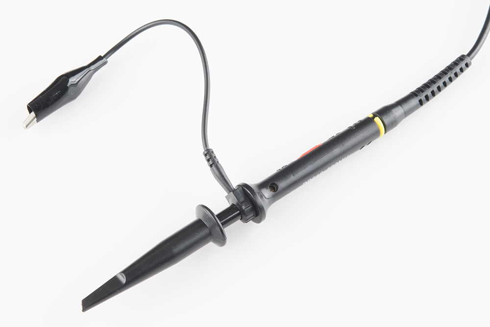
The Probes
An oscilloscope is only good if you can actually connect it to a signal, and for that you need probes. Probes are single-input devices that route a signal from your circuit to the scope. They have a sharp tip which probes into a point on your circuit. The tip can also be equipped with hooks, tweezers or clips to make latching onto a circuit easier. Every probe also includes a ground clip, which should be secured safely to a common ground point on the circuit under test.
While probes may seem like simple devices that just latch onto your circuit and carry a signal to the scope, there’s actually a lot that goes into probe design and selection.
Optimally, what a probe needs to be is invisible – it shouldn’t have any effect on your signal under test. Unfortunately, long wires all have intrinsic inductance, capacitance, and resistance, so, no matter what, they’ll affect scope readings (especially at high frequencies).
There are a variety of probe types out there, the most common of which is the passive probe, included with most scopes. Most of the “stock” passive probes are attenuated. Attenuating probes have a large resistance intentionally built-in and shunted by a small capacitor, which helps to minimize the effect that a long cable might have on loading your circuit. In series with the input impedance of a scope, this attenuated probe will create a voltage divider between your signal and the scope input.
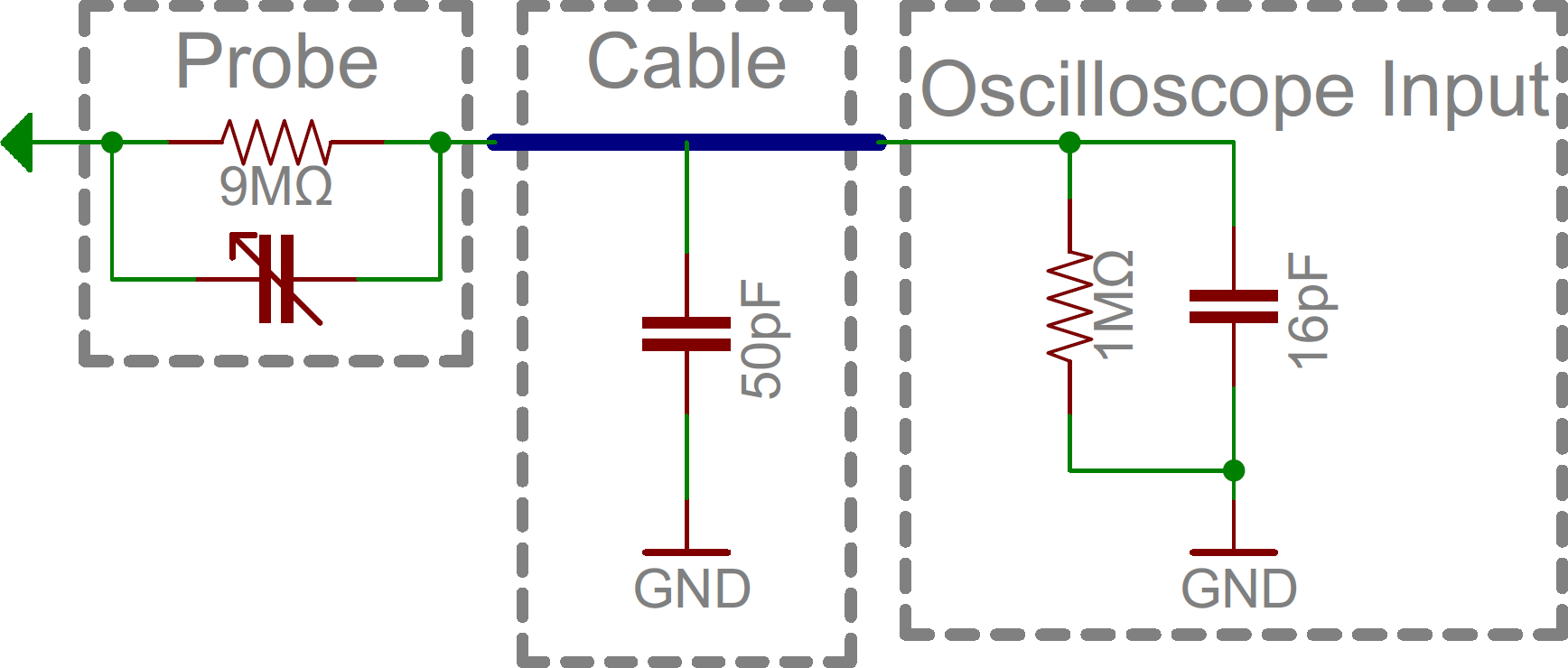
Most probes have a 9MΩ resistor for attenuating, which, when combined with a standard 1MΩ input impedance on a scope, creates a 1/10 voltage divider. These probes are commonly called 10X attenuated probes. Many probes include a switch to select between 10X and 1X (no attenuation).
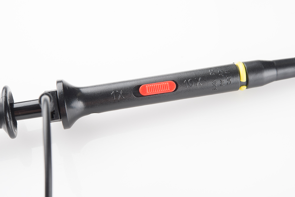
Attenuated probes are great for improving accuracy at high frequencies, but they will also reduce the amplitude of your signal. If you’re trying to measure a very low-voltage signal, you may have to go with a 1X probe. You may also need to select a setting on your scope to tell it you’re using an attenuated probe, although many scopes can automatically detect this.
Beyond the passive attenuated probe, there are a variety of other probes out there. Active probes are powered probes (they require a separate power source), which can amplify your signal or even pre-process it before it get to your scope. While most probes are designed to measure voltage, there are probes designed to measure AC or DC current. Current probes are unique because they often clamp around a wire, never actually making contact with the circuit.