How to Use an Oscilloscope
 jimblom
Using an Oscilloscope
The infinite variety of signals out there means you'll never operate an oscilloscope the same way twice. But there are some steps you can count on performing just about every time you test a circuit. On this page we'll show an example signal, and the steps required to measure it.
Probe Selection and Setup
First off, you'll need to select a probe. For most signals, the simple passive probe included with your scope will work perfectly fine.
Next, before connecting it to your scope, set the attenuation on your probe. 10X -- the most common attenuation factor -- is usually the most well-rounded choice. If you're trying to measure a very low-voltage signal though, you may need to use 1X.
Connect the Probe and Turn the Scope On
Connect your probe to the first channel on your scope, and turn it on. Have some patience here, some scopes take as long to boot up as an old PC.
When the scope boots up you should see the divisions, scale, and a noisy, flat line of a waveform.
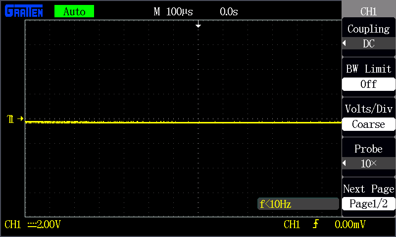
The screen should also show previously set values for time and volts per div. Ignoring those scales for now, make these adjustments to put your scope into a standard setup:
- Turn channel 1 on and channel 2 off.
- Set channel 1 to DC coupling.
- Set the trigger source to channel 1 -- no external source or alternate channel triggering.
- Set the trigger type to rising edge, and the trigger mode to auto (as opposed to single).
- Make sure the scope probe attenuation on your scope matches the setting on your probe (e.g. 1X, 10X).
For help making these adjustments, consult your scope's user's manual (as an example, here's the GA1102CAL manual).
Testing the Probe
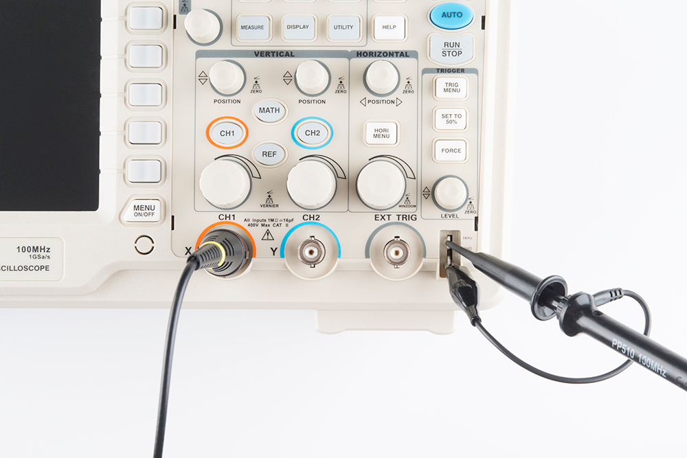
Let's connect that channel up to a meaningful signal. Most scopes will have a built-in frequency generator that emits a reliable, set-frequency wave -- on the GA1102CAL there is a 1kHz square wave output at the bottom-right of the front panel. The frequency generator output has two separate conductors -- one for the signal and one for ground. Connect your probe's ground clip to the ground, and the probe tip to the signal output.
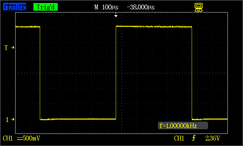
As soon as you connect both parts of the probe, you should see a signal begin to dance around your screen. Try fiddling with the horizontal and vertical system knobs to maneuver the waveform around the screen. Rotating the scale knobs clockwise will "zoom into" your waveform, and counter-clockwise zooms out. You can also use the position knob to further locate your waveform.
If your wave is still unstable, try rotating the trigger position knob. Make sure the trigger isn't higher than the tallest peak of your waveform. By default, the trigger type should be set to edge, which is usually a good choice for square waves like this.
Try fiddling with those knobs enough to display a single period of your wave on the screen.
Or try zooming way out on the time scale to show dozens of squares.
Compensating an Attenuated Probe
If your probe is set to 10X, and you don't have a perfectly square waveform as shown above, you may need to compensate your probe. Most probes have a recessed screw head, which you can rotate to adjust the shunt capacitance of the probe.

Try using a small screwdriver to rotate this trimmer, and look at what happens to the waveform.
Adjust the trimming cap on the probe handle until you have a straight-edged square wave. Compensation is only necessary if your probe is attenuated (e.g. 10X), in which case it's critical (especially if you don't know who used your scope last!).
Probing, Triggering, and Scaling Tips
Once you've compensated your probe, it's time to measure a real signal! Go find a signal source (frequency generator?, Terror-Min?) and come back.
The first key to probing a signal is finding a solid, reliable grounding point. Clasp your ground clip to a known ground, sometimes you may have to use a small wire to intermediate between the ground clip and your circuit's ground point. Then connect your probe tip to the signal under test. Probe tips exist in a variety of form factors -- the spring-loaded clip, fine point, hooks, etc. -- try to find one that doesn't require you to hold it in place all the time.
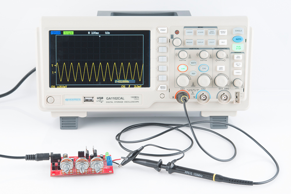
Once your signal is on the screen, you may want to begin by adjusting the horizontal and vertical scales into at least the "ballpark" of your signal. If you're probing a 5V 1kHz square wave, you'll probably want the volts/div somewhere around 0.5-1V, and set the seconds/div to around 100µs (14 divisions would show about one and a half periods).
If part of your wave is rising or falling of the screen, you can adjust the vertical position to move it up or down. If your signal is purely DC, you may want to adjust the 0V level near the bottom of your display.
Once you have the scales ballparked, your waveform may need some triggering. Edge triggering -- where the scope tries to begin its scan when it sees voltage rise (or fall) past a set point -- is the easiest type to use. Using an edge trigger, try to set the trigger level to a point on your waveform that only sees a rising edge once per period.
Now just scale, position, trigger and repeat until you're looking at exactly what you need.
Measure Twice, Cut Once
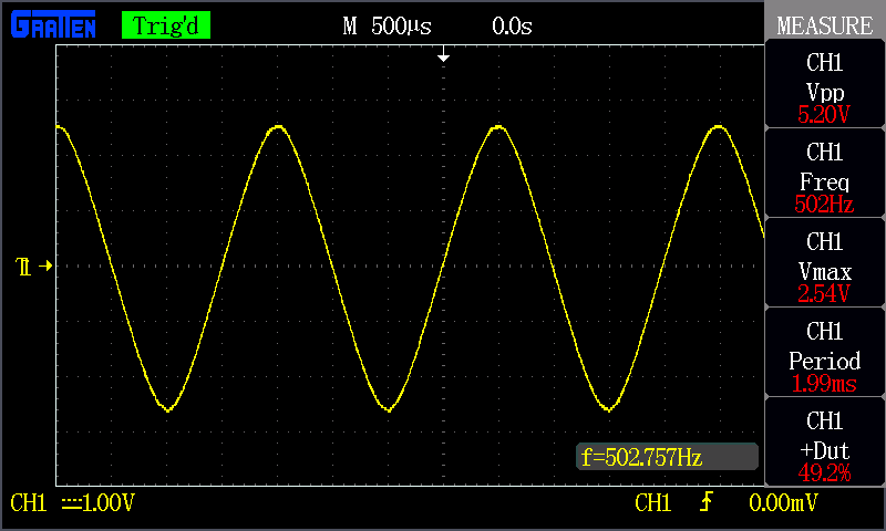
With a signal scoped, triggered, and scaled, it comes time to measure transients, periods, and other waveform properties. Some scopes have more measurement tools than others, but they'll all at least have divisions, from which you should be able to at least estimate the amplitude and frequency.
Many scopes support a variety of automatic measurement tools, they may even constantly display the most relevant information, like frequency. To get the most out of your scope, you'll want to explore all of the measure functions it supports. Most scopes will calculate frequency, amplitude, duty cycle, mean voltage, and a variety of other wave characteristics for you automatically.
A third measuring tool many scopes provide is cursors. Cursors are on-screen, movable markers which can be placed on either the time or voltage axis. Cursors usually come in pairs, so you can measure the difference between one and the other.

Once you've measured the quantity you were looking for, you can begin to make adjustments to your circuit and measure some more! Some scopes also support saving, printing, or storing a waveform, so you can recall it and remember those good ol' times when you scoped that signal.
To find out more about what your scope can do, consult its user's manual!