INA169 Breakout Board Hookup Guide
 Shawn Hymel
Example Code
Open the Arduino program and paste the following code into the sketch:
language:c
/*
 11-14-2013
 SparkFun Electronics 2013
 Shawn Hymel

 This code is public domain but you buy me a beer if you use this
 and we meet someday (Beerware license).

 Description:

 This sketch shows how to use the SparkFun INA169 Breakout
 Board. As current passes through the shunt resistor (Rs), a
 voltage is generated at the Vout pin. Use an analog read and
 some math to determine the current. The current value is
 displayed through the Serial Monitor.

 Hardware connections:

 Uno Pin    INA169 Board    Function

 +5V        VCC             Power supply
 GND        GND             Ground
 A0         VOUT            Analog voltage measurement

 VIN+ and VIN- need to be connected inline with the positive
 DC power rail of a load (e.g. an Arduino, an LED, etc.).

 */

// Constants
const int SENSOR_PIN = A0;  // Input pin for measuring Vout
const int RS = 10;          // Shunt resistor value (in ohms)
const int VOLTAGE_REF = 5;  // Reference voltage for analog read

// Global Variables
float sensorValue;   // Variable to store value from analog read
float current;       // Calculated current value

void setup() {

  // Initialize serial monitor
  Serial.begin(9600);

}

void loop() {

  // Read a value from the INA169 board
  sensorValue = analogRead(SENSOR_PIN);

  // Remap the ADC value into a voltage number (5V reference)
  sensorValue = (sensorValue * VOLTAGE_REF) / 1023;

  // Follow the equation given by the INA169 datasheet to
  // determine the current flowing through RS. Assume RL = 10k
  // Is = (Vout x 1k) / (RS x RL)
  current = sensorValue / (10 * RS);

  // Output value (in amps) to the serial monitor to 3 decimal
  // places
  Serial.print(current, 3);
  Serial.println(" A");

  // Delay program for a few milliseconds
  delay(500);

}
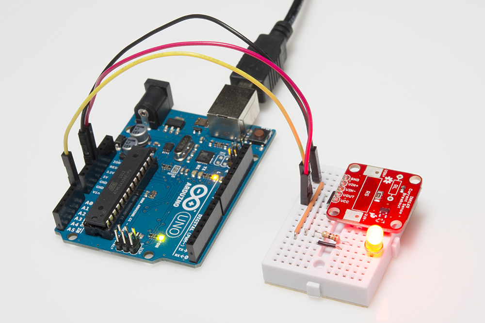
Plug in the Arduino and upload the code. You should see the LED light up as soon as you apply power.
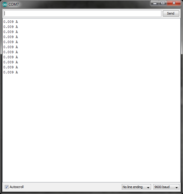
Select the appropriate board (Arduino Uno in this case) from Tools->Board and the correct COM port from Tools->Serial Port. Click the upload button, and wait for the program to be compiled and uploaded to the Arduino. Open the Serial Monitor from Tools->Serial Monitor and you should see current measurements being printed.
If we want to verify this reading, we can use a multimeter to measure the voltage across the 330Ω resistor. You should see around 3V across the resistor. Using Ohm's Law, we can calculate the current flowing through the resistor and LED is 0.00909 A, which matches the reading from the INA169.