Installing a Bootloader on the MicroView
 jimblom
(Carefully) Opening the Case
The AVR ISP programming interface requires six pins: VCC, GND, RST, MOSI, MISO, and SCK. VCC (power), GND (ground), and RST (reset) are all broken somewhere along the MicroView's readily available pair of 8-pin headers. Unfortunately, the three SPI signals are not broken out to the headers, they're tucked away, inside the enclosure, broken out to three unmasked vias. To expose these pins, you'll have to remove the Microview's covering lens and lift the display up.
Grab your spudger, hobby knife or small, flathead screwdriver. And find a flat, steady surface to do the deed.
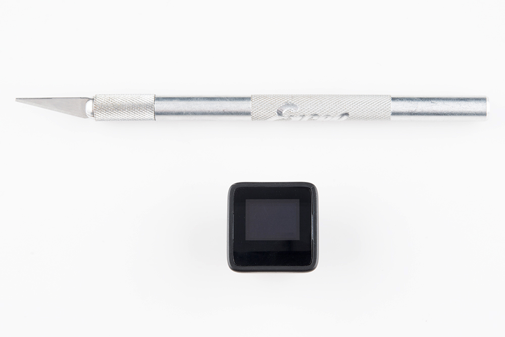
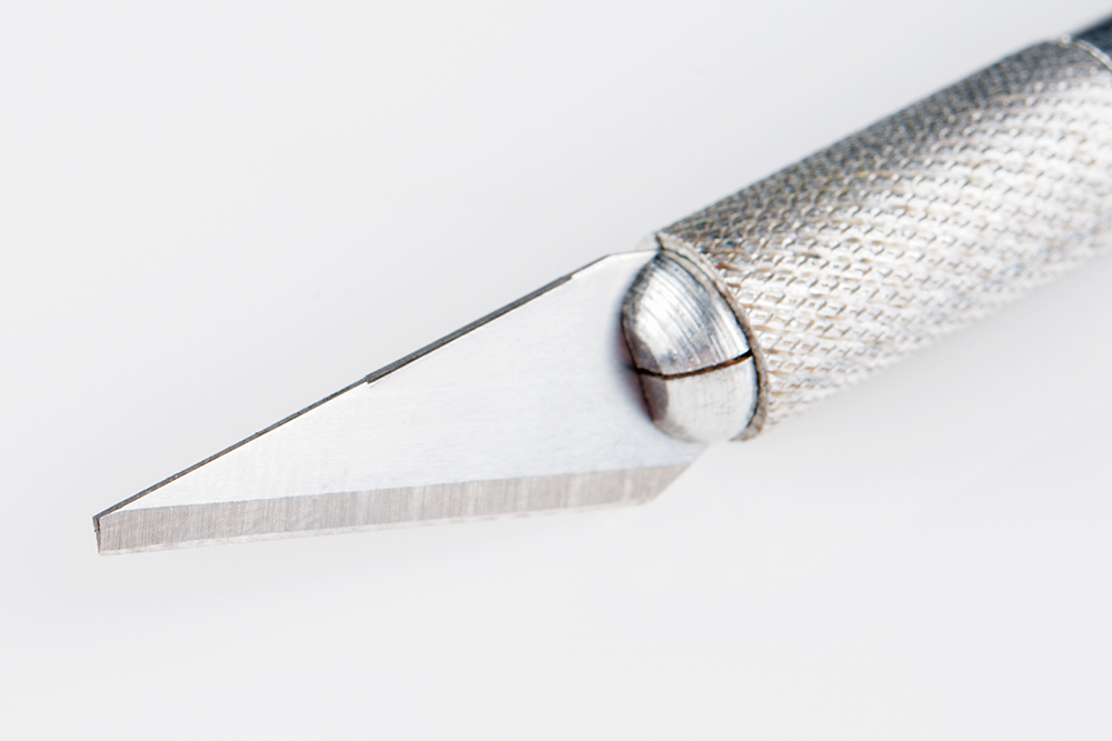
If you're using a sharp-edged hobby knife, you may want to grab a pair of pliers and snap off a small chunk of the tip to get a more blunt, flat edge.
The lens cover is held in place by two securing notches on the left and right sides of the enclosure. Try to expose as much of a gap on one side as you can, by sliding the lens to either the left or right. You may be able to see one of the securing notches.
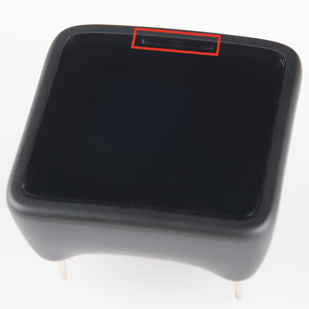
Insert your opener somewhere between that notch and the bottom of the cover. You should be able to push it in about 2mm, before a beveled edge inside the enclosure gets in the way. Be gentle, but try to push in as far as you can to get more leverage.
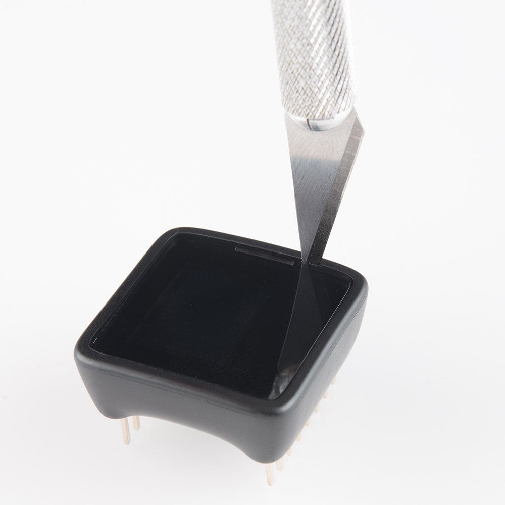
Then pry up the cover by tilting the opener towards the outside of the MicroView.
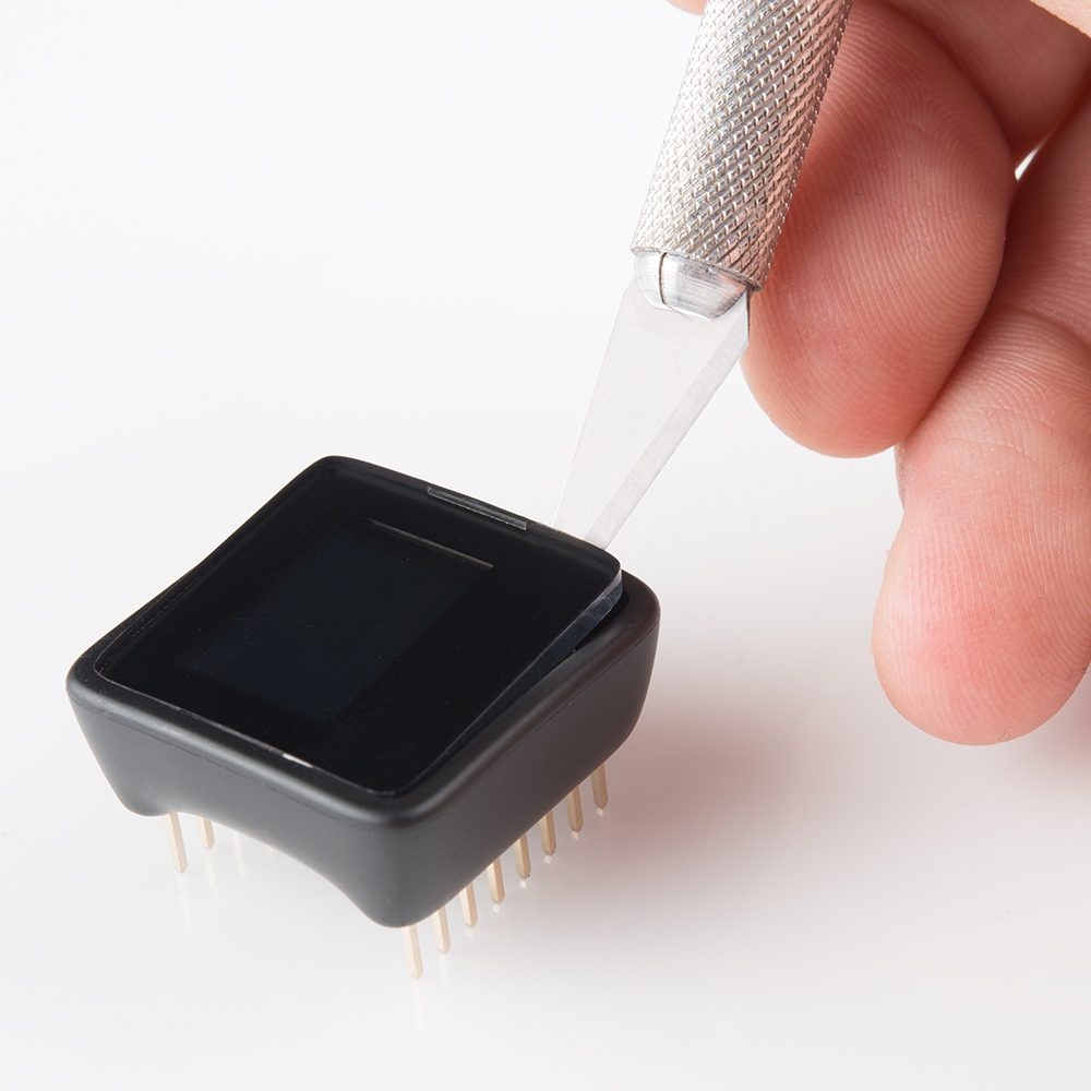
Once the edge of the screen has popped off, grab it with your fingers and pull it off.
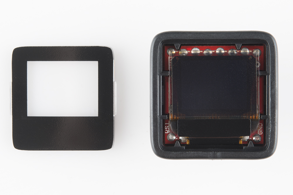
The exposed pins for MISO, MOSI, and SCK are just under the display. To access them, very carefully pry the OLED up. The OLED is connected to the PCB via a thin, black connector; it's fragile, take great care not to place any extra stress on it.

Those three, small unmasked vias, labeled "11", "12", and "13", are what we're after!