Installing a Bootloader on the MicroView
 jimblom
Wiring the MicroView
You've wired up to the programmer, that's (the easier) half of the wiring. Now to wire up the MicroView. To begin, plug your MicroView into the USB Programmer, then plug the Programmer into a breadboard.
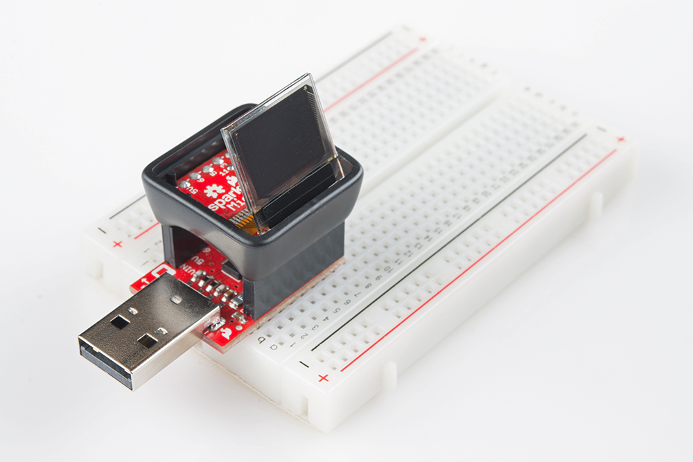
The breadboard will be useful as both a wire tie-in point and as a steadying tool.
Power and Reset
The VCC, GND, and RST pins are, fortunately, all broken out on the Microview.
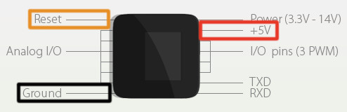
Wiring those to your programmer is as simple as plugging some wires into a breadboard.
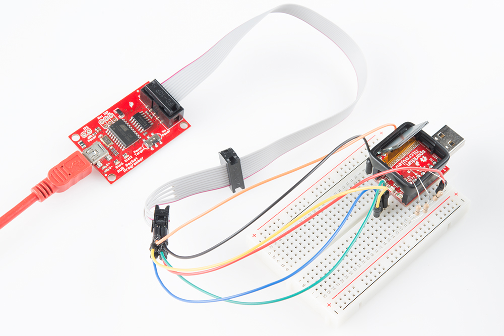
This is a good time to think about how you're going to power the MicroView as it's being programmed. Some programmers -- including the ArduinoISP, Tiny AVR Programmer, and AVR Pocket Programmer -- can power the MicroView by themselves. Other programmers (like more official Atmel AVR ISPs) require the MicroView be powered externally. If you need to externally power the MicroView, plug the USB Programmer into your computer. But, if you're going to power the MicroView from your AVR programmer, leave your MicroView's USB Programmer unplugged.
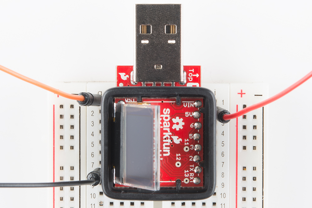
Connecting to MOSI, MISO, and SCK (11, 12, and 13)
Now the hard part. We need to connect the three SPI lines as follows:
| Programmer Pin | MicroView Pin |
|---|---|
| MOSI (D11) | 11 |
| MISO (D12) | 12 |
| SCK (D13) | 13 |
Having gone through this process more than a few times, here are three possible methods we've gotten to work. Click to skip to the respective section:
- Soldering wires to vias -- With soldering tools and a careful hand, you can solder jumper wires directly to the vias. This is the most reliable method, but also requires the most tools -- not recommended for a beginning solderer.
- Inserting 0Ω Resistors -- If you have 0Ω "jumper" resistors (like those in our Resistor Kit), and their legs are skinny enough, you can plug them into the MicroView's vias. This is a relatively reliable, temporary solution.
- Holding wires in place -- Short of any other option, you can try holding all three wires in place, as you burn the bootloader. This method works, but requires some patience and steady hands.
Soldering the Wires
If you have a soldering iron handy, we recommend connecting the jumper wires to the vias with a small dab of solder. If you're taking a soldering iron to your MV, you may want to lift the entire board out of the enclosure to avoid burning the edges. Press down on the MicroView's enclosure, using the table to push the header pins up, it'll take a steady amount of force to unseat the PCB from its retaining clips.
Apply a dab of solder to the vias.
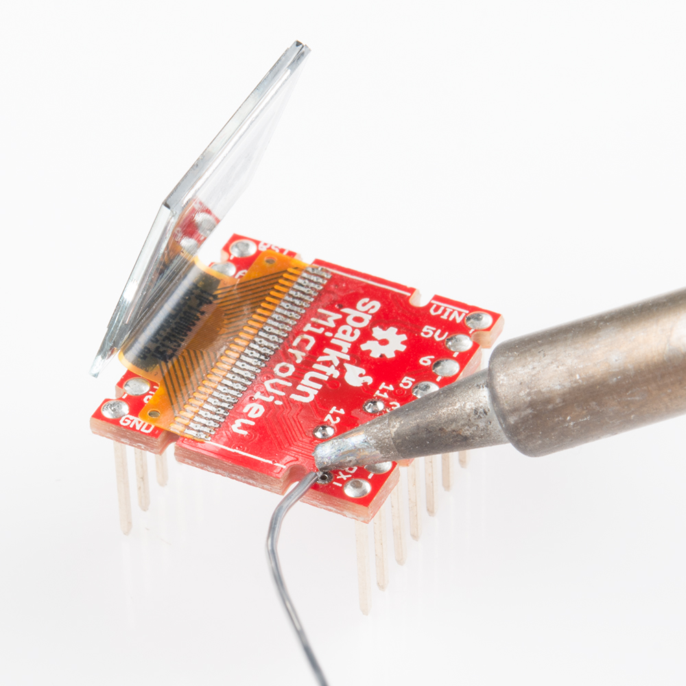
Then heat the solder dab back up and fuse an end of the jumper wire to it. Repeat that process for each of the three vias.
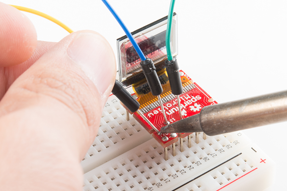
After the wire is soldered, take care to not to let it pull on the MicroView too hard. You'll risk lifting the via and its copper of the board entirely (then you'll be left to soldering to the ATmega328P's pins).
Plug those wires into the correct port of your programmer:
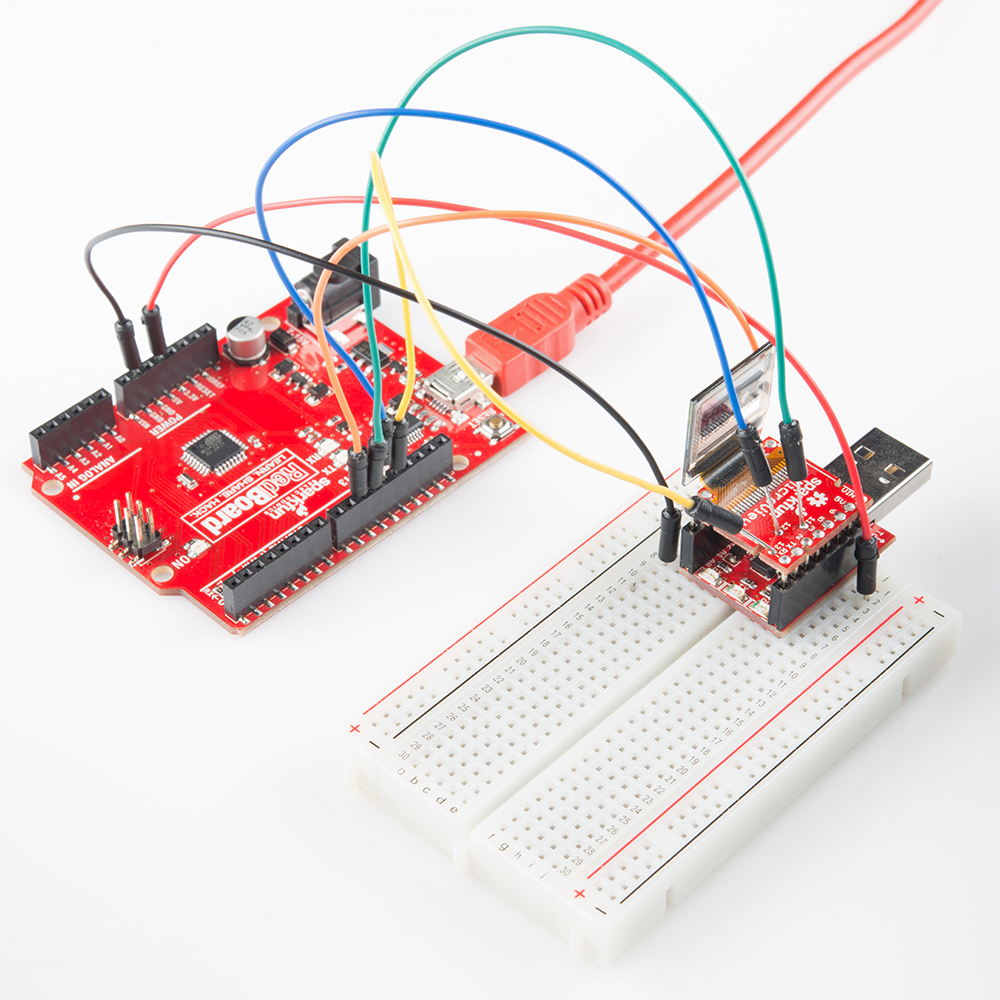
Then skip to the next section.
Connecting via 0Ω Resistors (Or Thin Solid Wires)
If you're lacking for soldering tools, or just want to avoid altering your MicroView, see if you can grab three 0Ω (or at the very least very small, <50Ω) resistors. Those included in our Resistor Kit work perfectly. You may have to dig around to find a resistor with thin enough terminations, they'll need to be less than about 0.015" to fit in the MicroView's vias.
Plug each of the resistors into a different via on the MicroView, then plug the other end of the resistor into a unique row on the breadboard.
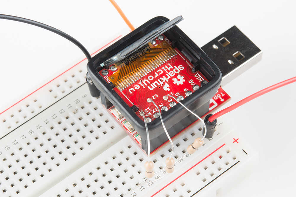
Then route each of the programmer's SPI pins to the appropriate row in the breadboard. You may need to just slightly bend the resistor at the point that it hits the via -- just enough for it to make an electrical contact.
We're teetering on the edge of reliability here, but this option is still worlds better than the next...
"Push-Connecting" the Wires
If you don't have either soldering tools or low-impedance resistors, you better have dexterity, a steady hand, and patience. You can "poke" each of the three jumper wires into their respective vias, creating just enough of an electrical connection. We really recommend asking a buddy to help you out here, because while one hand is busy holding the wires in place, the other will have to be on your computer mouse, clicking through menus.
Before actually pushing the wires into place, click over to the next page and get fully prepared to program your bootloader. Once your mouse cursor is hovering over "Burn Bootloder" in the Arduino IDE, then you can start fussing with push-connecting your jumper wires.
There are no real tricks to this. Begin by pushing a wire into pin 13. Once that's steady continue on to pin 12, holding both jumpers between thumb and forefinger. Finally add pin 11.
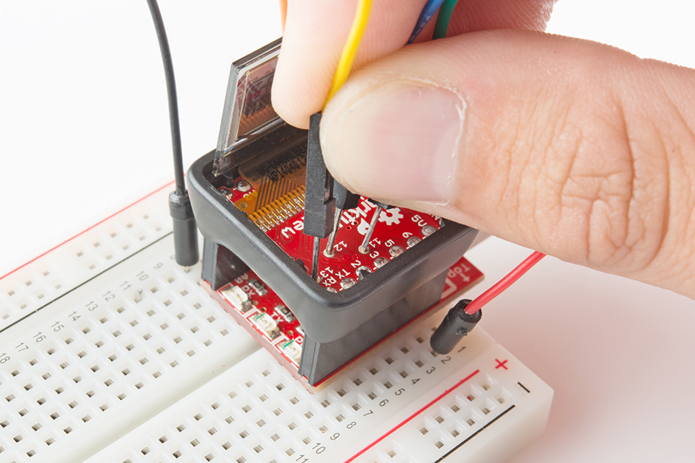
Then quickly start programming! You'll have to hold them in place for about 30 seconds.