Installing a Bootloader on the MicroView
 jimblom
Wiring the Programmer
As evidenced by our list of devices in the "Programmer" part of the "Gathering the Tools" section, there is no shortage of boards that can program a bootloader. In this section we'll demonstrate how to hook up a few of the most common programming tools.
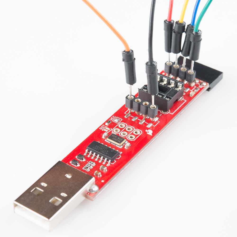
For each, we'll have to wire up six signals: VCC, GND, Reset, MOSI, MISO, and SCK. We'll use the following color coded wires for the six signals:
| Signal Name | MicroView Pin | Wire Color |
|---|---|---|
| VCC | 5V | Red |
| GND | GND | Black |
| Reset | RST | Orange |
| MOSI | 11 | Green |
| MISO | 12 | Blue |
| SCK | 13 | Yellow |
We will repeat the hookup for each programmer, click below if you want to skip to a particular device:
- An AVR Pocket Programmer (or any dedicated AVR Programmer with a 2x3 ISP cable)
- A Tiny AVR Programmer
- An Arduino equipped with the ArduinoISP sketch.
Connecting to an AVR ISP 2x3 Cable
Before connecting the programmer to your MicroView, you may need to install drivers. If you're using the AVR Pocket Programmer, follow along with our Pocket AVR Programmer Hookup Guide for guidance.
Most AVR development boards, like the Arduino Uno, break out a 2x3 header specifically geared towards (re)programming via ISP. This header matches up to a standardized 2x3 ISP footprint (or a larger 2x5 variant) with the following pinout:
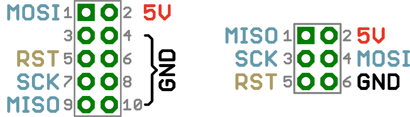
Those pinouts are a top-view of the connector as it would be on the PCB. If you're plugging wires into the cable, you need to flip that image over the horizontal. Here's how those signals are routed on the cable connector:
Note that the notch in the cable indicates the pin-1 side of the footprint.
Unfortunately, the MicroView PCB wasn't big enough to fit the whole standardized ISP header, but, once you've removed the cover, all of the pins you need are exposed in one way or another.
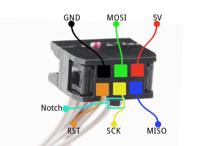
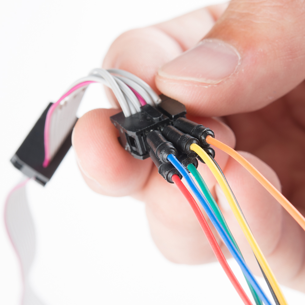
Plug your six jumper cables straight into the 2x3 connector. Use color-coded wires if you can. Here's where each ISP pin goes (note the notch, indicating the pin 1 side):
Then skip to the Wiring to the MicroView section to complete the wiring.
Connecting to the Tiny AVR Programmer
The Tiny AVR Programmer is a tool built for programming ATtiny85's, but it's more multi-purpose than that! It can program any AVR. If you're approaching this task with the Tiny AVR Programmer, make sure you've read through our Tiny AVR Programmer Hookup Guide -- at least through the driver installation section.
The Tiny AVR Programmer doesn't mate to a standard 2x3 connector, the pins we'll need are all broken out to both the 8-pin DIP socket and the two 4-pin machine-pin connectors. Here's what's what:
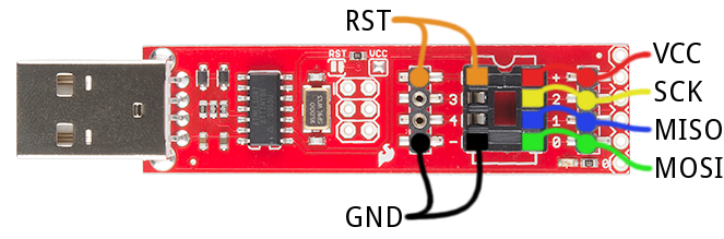
Insert your wires. Color code them if you can.
Then proceed to the Wiring to the MicroView section.
Connecting to an ArduinoISP
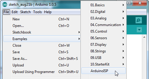
Just about any, old Arduino can be turned into an AVR ISP. All you need is the right sketch: ArduinoISP, which is included by default with the Arduino IDE. Open the sketch by going to File > Examples > ArduinoISP. Then upload it to your Arduino, which fortunately already has a bootloader!
The ArduinoISP sketch uses Arduino pins 10, 11, 12, and 13 as RST, MOSI, MISO, and SCK, respectively. If you're using an Arduino Uno, you may also need to connect a 10µF capacitor between the reset pin and ground. Here's how it'll be wired up to the MicroView:

Note that the ArduinoISP sketch does provide for some simple debugging by assigning LEDs to pins 7, 8, and 9. They're completely optional, but can make tracking down errors a bit easier. An LED on pin 9 will indicate a "heartbeat", 8 will blink if there's an error, and pin 7 will indicate that programming is in process.
Use some color-coded jumpers to wire it up, like this:
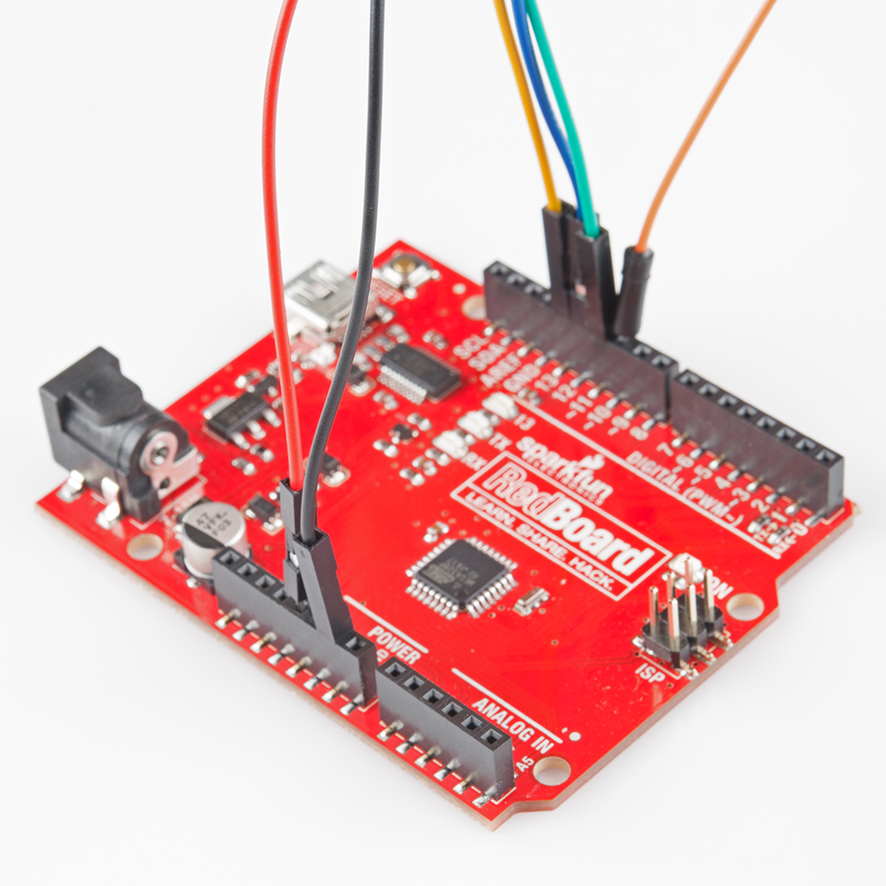
Then proceed to the next section, to wire it up to the MicroView.