Installing an Arduino Bootloader
 M-Short
 Hardware Hookup
In-Circuit Serial Programming (ICSP)
It's very uncommon to program ICs before they are soldered onto a PCB. Instead, most microcontrollers have what's called an in-system programming (ISP) header. Particularly, some IC manufacturers, such as Atmel and Microchip, have a specialized ISP method for programming their ICs. This is referred to as in-circuit serial programming (ICSP). Most Arduino and Arduino compatible boards will have a 2x3 pin ICSP header on them. Some may even have more than one depending on how many ICs live on the PCB. It breaks out three of the SPI pins (MISO, MOSI, SCK), power, ground, and reset. These are the pins you'll need to connect your programmer to in order to reflash the firmware on your board.
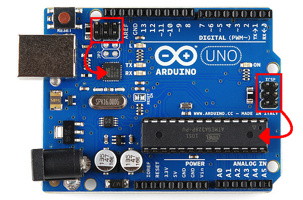
On some smaller boards you may not see this connector, but the pins should be broken out elsewhere. Whether you're using an SMD IC or a DIP IC, the ISP pins should be accessible in one form or another. Some boards might only have test points for the ISP header. If this is the case, you may want to consider getting an ISP Pogo Adapter. This kit allows you to temporarily make a good connection with test test points in order to reprogram your IC.
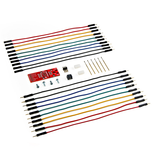
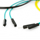
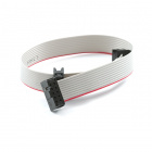
Once you have located the six ICSP pins on your board, it's time to hook up your programmer to the board. You can use a programming cable to connect the two, or, if you don't have a cable, you can just use some male-to-female jumper wires.
Connecting the Pocket AVR Programmer to Target
If you are using a programmer such as the pocket AVR programmer, your setup should look something like the connection below with the AVR programming cable's arrow (◄) connected to MISO. If you look really closely at the molding of the 2x3 connector, you should be able to notice the arrow (◄) pointing to pin 1 relative to the position of a standard ICSP header.
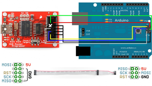

You also might notice that there is not a USB cable connected to one of the RedBoards. Since the pocket AVR programmer can provide 5V power to the target AVR with the switch flipped to the Power Target position, a USB cable is not needed for the RedBoard. However, the official Atmel AVR MKII is not able to provide power to the target board. Thus, a cable is required to connect to the target AVR.
The same goes for newer Atmel programmers. The image below shows the Atmel JTAG ICE3 connected to a RedBoard. As you can see, the position of the AVR cable is connected to the RedBoard similar to the image with the AVR MKII. Since the programmer is not able to provide power to the target, you would need an additional cable connected to the target AVR.

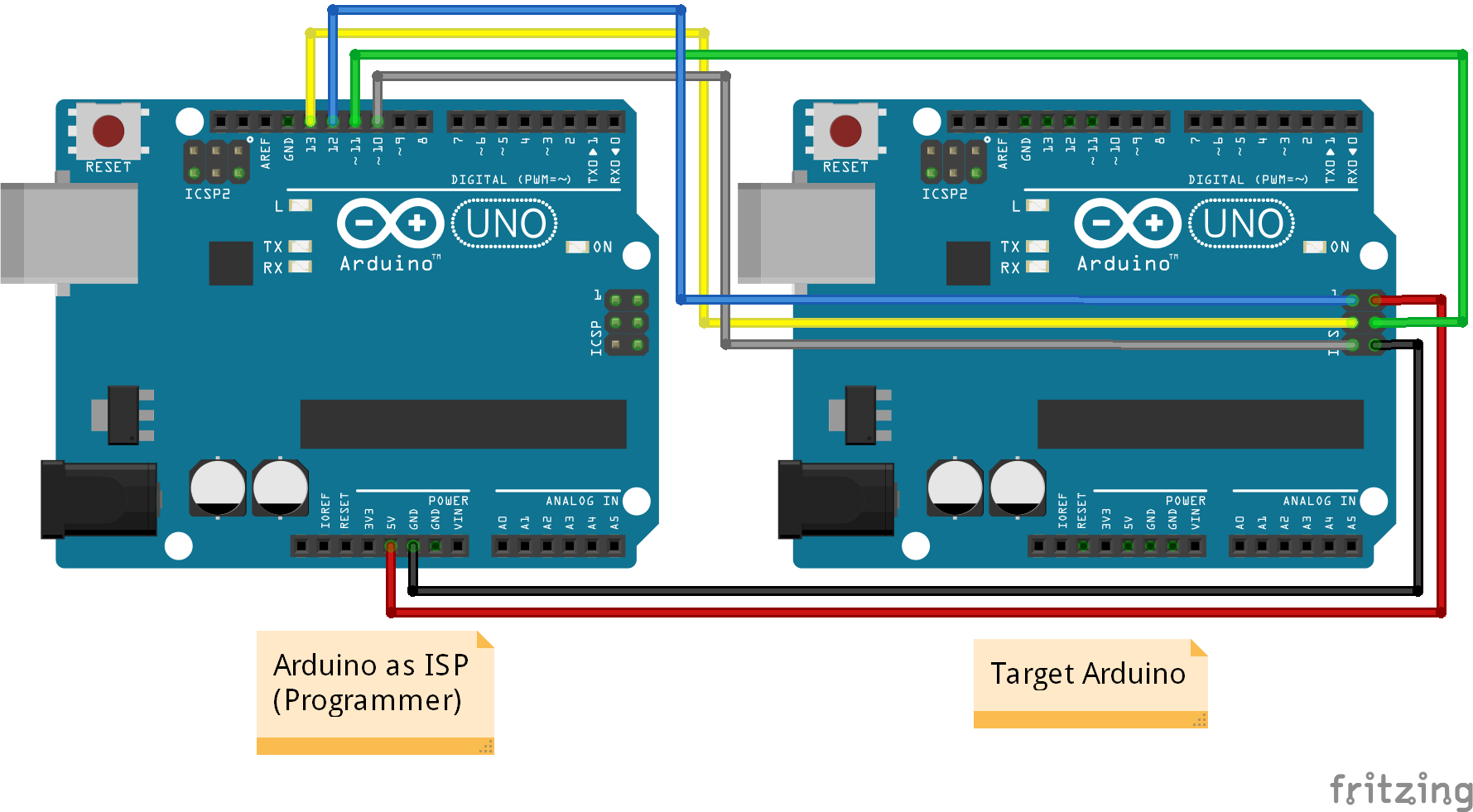
Connecting the Arduino as ISP to Target
Or, if you're using the Arduino as your programmer, it should look the image below. Make sure to power the Arduino as ISP by connecting it to your computer.
Hookup Table
Here's a table to help clarify which connections go where. Depending on the Arduino, you may have access to the ICSP pins only on the 2x3 ICSP header. Make sure to refer to the board layout for more information on the Arduino's SPI connections.
| AVR Programmer | Arduino as ISP | 2x3 ICSP Header | ATmega328 | ATmega2560 | ATmega32U4 |
|---|---|---|---|---|---|
| 5V | Vcc/5V | Pin 2 | Vcc | Vcc | Vcc |
| GND | GND | Pin 6 | GND | GND | GND |
| MOSI | MOSI/D11 | Pin 4 | D11 | D51 | D16 |
| MISO | MISO/D12 | Pin 1 | D12 | D50 | D14 |
| SCK | SCK/D13 | Pin 3 | D13 | D52 | D15 |
| Reset | D10 | Pin 5 | Reset | Reset | Reset |
