IR Communication
Hardware Hookup
For the hardware in this tutorial, you will need the following materials. You may not need everything though depending on what you have. Add it to your cart, read through the guide, and adjust the cart as necessary.
You will be setting up two separate circuits both using an Arduino. The first example circuit uses a TSOP382 IR photo sensor to receive and demodulate the IR signal from a common remote control. The second example circuit uses a 950nm IR LED and current limiting resistor to transmit IR codes to a common appliance, for example a home stereo or TV.
Circuit Diagram
Here is the complete setup for connecting to an Arduino:
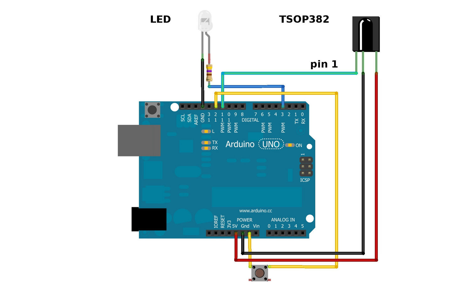
Be sure to connect your LED correctly! The long leg is positive and connects to the resistor, then to the Arduino’s output pin. The short leg is negative and is connected to ground (GND).
Also, you cannot see IR LED light with your eyes, since IR radiation is outside of the visible spectrum. However, most cellphone cameras can detect short wave IR and can see the LED faintly glowing.

Also, pay attention to the polarity of the TSOP382. Refer to the TSOP382 datasheet for the pinout of the sensor.
The current limiting resistor attached to the LED can have values down to 100Ω (40mA) for full power and longest range. If you use a larger value resistor, the LED won't light as bright and your range will suffer. With a 330Ω resistor, you should be able to operate the IR LED across a dimly lit room.