ISL29125 RGB Light Sensor Hookup Guide
 JordanDee
Hardware Overview
The ISL29125 Breakout Board is quite simple in terms of parts. It consists of the sensor chip itself, two decoupling capacitors and 3 pull-up resistors for the I2C and interrupt lines.
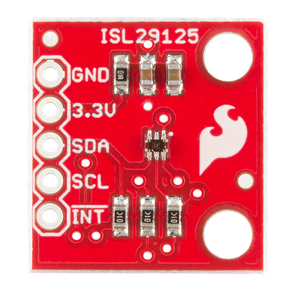
The main header is what allows you to interface with the board. Simply connect power (3.3V) and ground to the designated vias. Connect the I2C lines -- SDA and SCL -- to the corresponding pins on your microcontroller. If desired, you can also connect the !INT pin to a interrupt pin of your microcontroller. Make sure you use 3.3V for power and logic. The chip is not 5V tolerant and will be damaged if you apply 5V to power or any of the inputs. Use a logic level converter if you're controlling the chip with a 5V microcontroller.
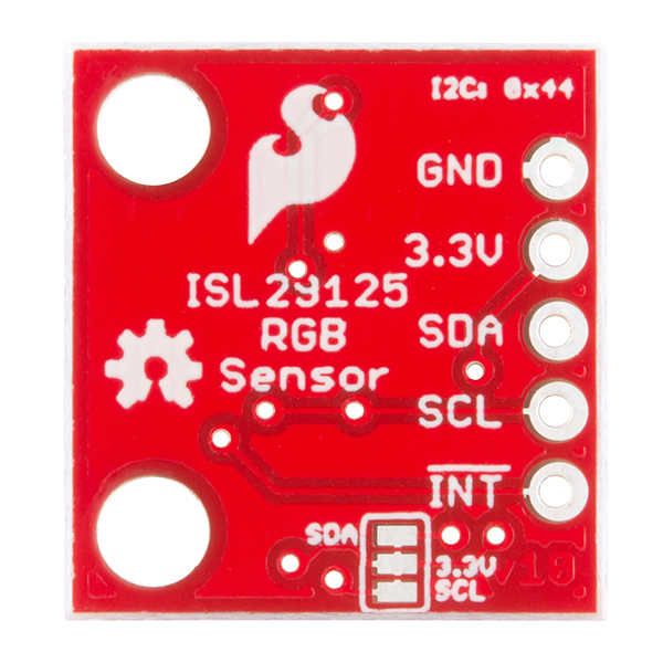
If you want to disable the on-board 10kΩ I2C pullup resistors -- in case you want to use those built into your microcontroller or other external pull-ups -- simply cut the two traces between the three pads on the backside of the board. If you decide you want the pull-ups later, you can always solder the pads back together.
Now that you're familiar with the board, let's get it up and running.