Jetson Nano + Sphero RVR Mash-up (PART 1)
 D___Run___
 Introduction
We finally jumped on a project that we have been wanting to do for a while now: a mash-up of two robotics kits that we released over the past year! Those kits are the Advanced Autonomous kit for the Sphero RVR and our AI JetBot kit for the NVIDIA Jetson Nano. Both projects were fun to work on during launch and both products have astounding quality in their own perspective markets so we're very excited to combine them together!
We set about building this mash-up and this tutorial as a guide for you to follow along with us in building your own Jetson Nano powered Sphero RVR. We built the bot almost entirely from parts found in the two kits with and placed on top of a Sphero RVR.
With all of this being said and documented if you choose to build your Nano RVR mash-up feel free to riff on what we did. There is no real right way to do this, it was us in the shop for an afternoon being creative. Your sensors, board placement and hardware choices may vary. Use this tutorial more as… “guidelines”.
Hardware Overview
As mentioned in the Introduction this project is a mash-up of two different kits, plus the Sphero RVR. We tried our best to source all of the parts individually for you, but many bits and pieces are used from the two original kits. Here is a wishlist of the major parts that would be required. In this case the only thing you would need to fabricate would be the camera mounting bracket if you dont have the one from the JetBot 2.1 kit.
Most of the hardware from each kit can be found in our catalog, but with a few bits and pieces thrown in as well. If you are sourcing parts individually rather than through our kits I have included the important parts we do not carry as individual components below.
Other Parts
3M Dual Lock - From the Jetbot AI Kit, I use it to mount the camera and battery
USB Battery Bank- For powering the Jetson Nano separate from the RVR, it comes with the Jetbot AI kit. If you source your own battery pack, make sure it can supply at least 3A@5V.
Mounting the NVIDIA Jetson Nano
Using the RVR as a platform for this robot enabled me to work with their topper plate system which makes building and fitting everything we needed onto the robot so much easier.
Instead of working around the robot and trying to figure out how to mount something and the repetitive task of bolting something down only to remove it again later, all I had to do was remove the topper plate and as long as it fit on that plate I knew it would mount on the robot without a problem.
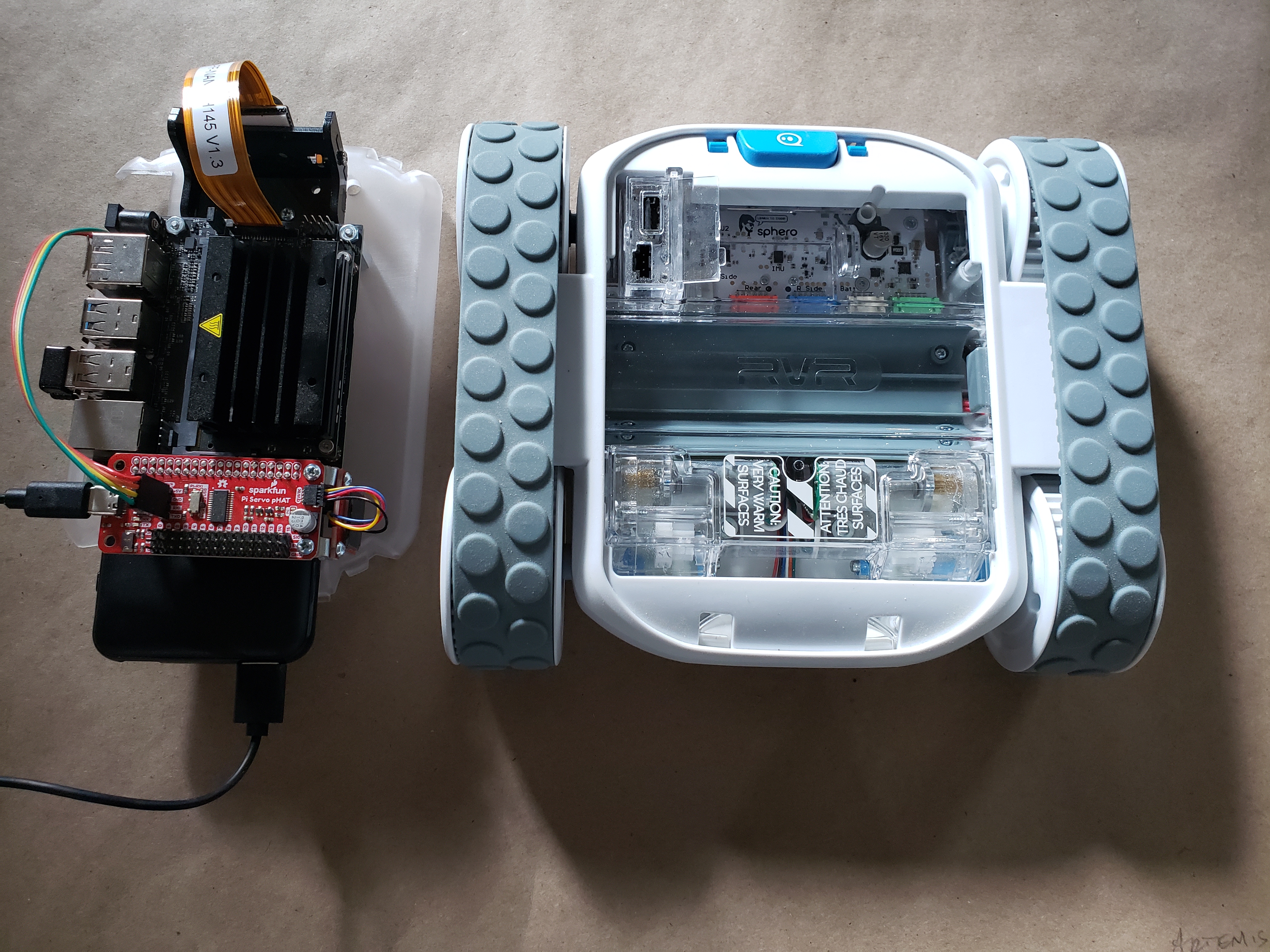
The RVR comes with a number of topper plates and one of them is specifically designed for mounting your own microcontrollers/single board computers to it. After trying a number of configurations of possible orientations of the Nano on the mounting plate I came to the conclusion that it wouldn't work for what I wanted to do. For this build I needed space to put the Nano and mount the camera while keeping wiring as clean as possible as well as space for the Servo pHAT or any other hardware connection to the GPIO headers in the rear of the robot.
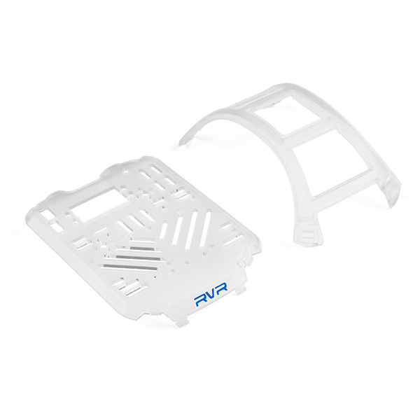
With all of that in mind there was only one option: modify the stock topper plate of the RVR to mount the Jetson Nano.
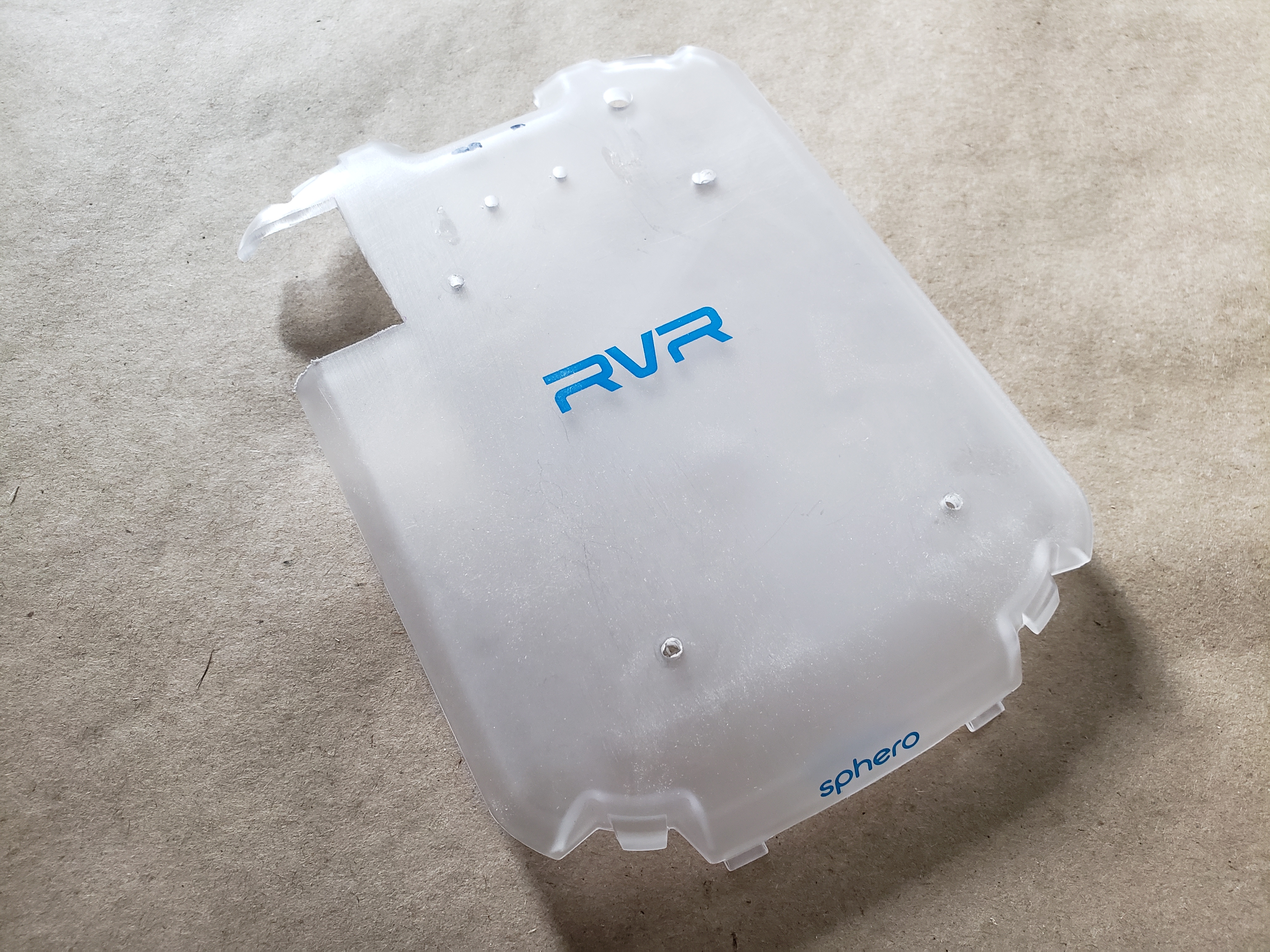
Planning for Mounting Holes
Before just going at it with a drill and making a few holes here and there, I wanted to be sure that I had all of the clearances needed underneath the build plate. I also needed to figure out what I would need to modify further so that I would have access to the UART/USB port of the RVR for hookup later.
I placed the Jetson Nano on the topper where I wanted it, and using an awl, I carefully marked the locations of the four mounting holes. You can do this with a super fine tip sharpie as well. I used an awl so that the small mark would be used as a pilot for when I drilled the four mounting holes later.
Serial / USB Port Access
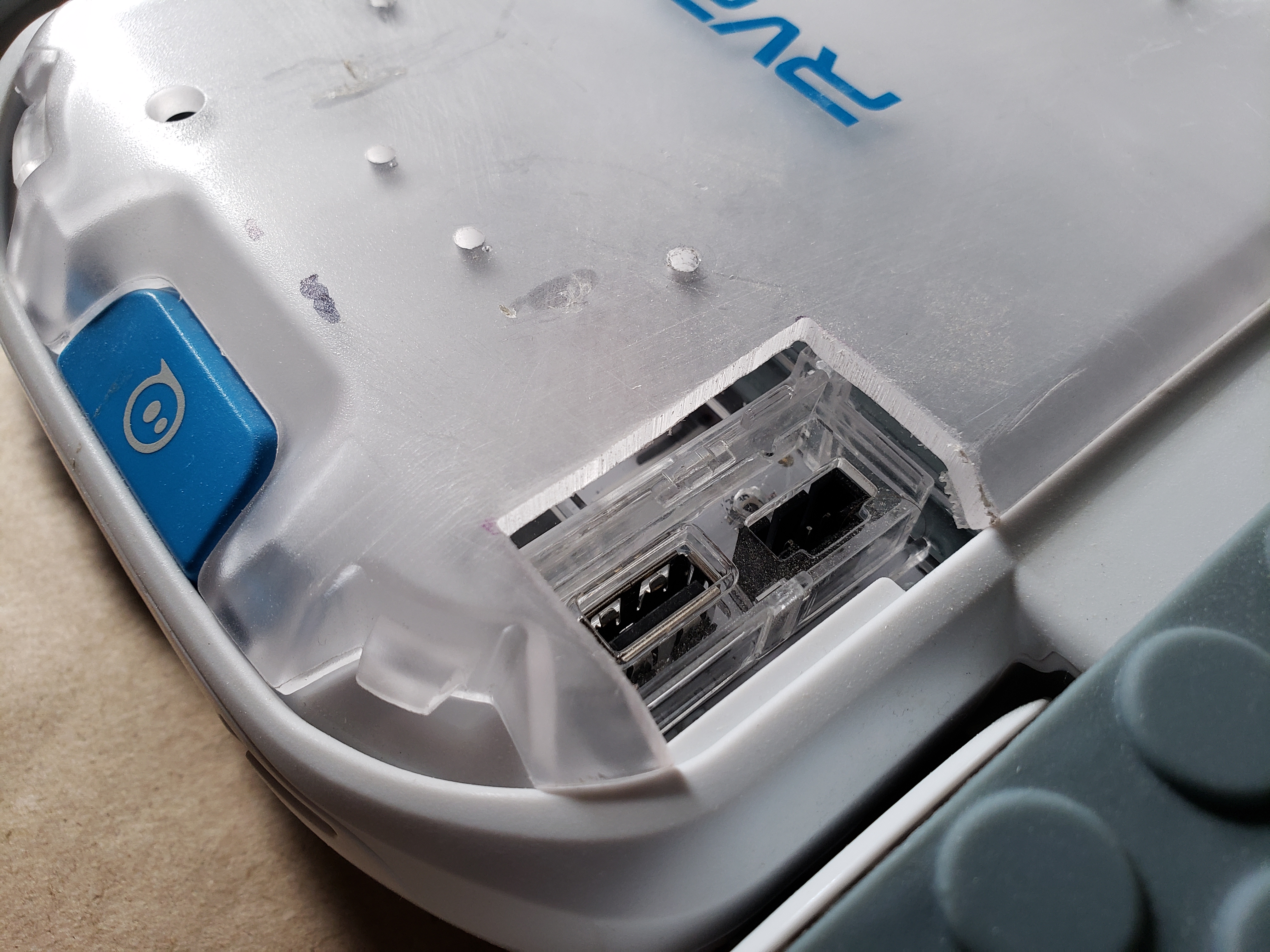
One of the downsides of using the basic topper plate for this project is that it doesn’t have any access to the USB / UART ports on the RVR. So, I had to make my own! With the plate mounted to the RVR, I could see the port through the translucent plastic and needed to cut that section of the topper away to have access to the port.
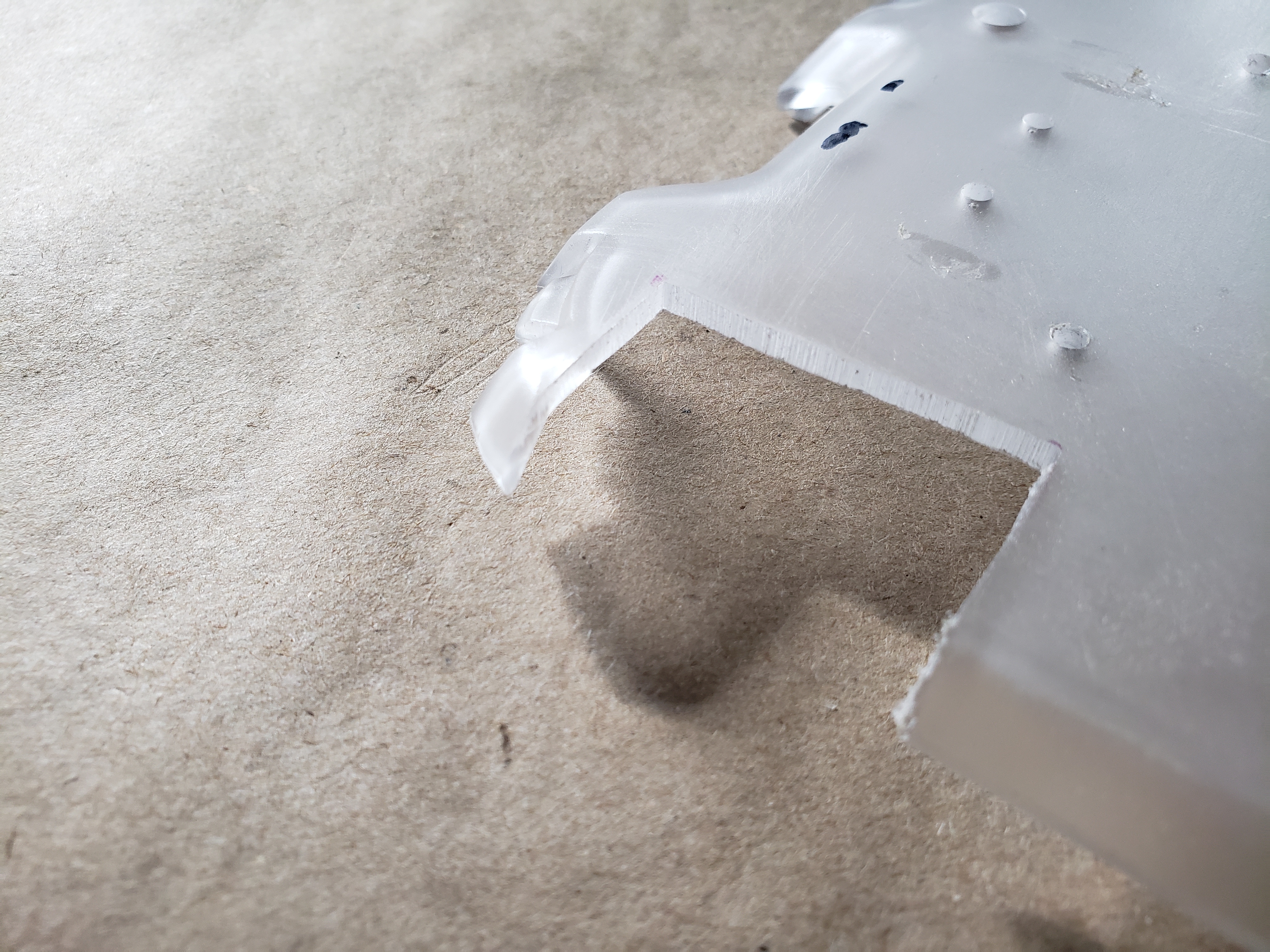
I marked the corners as best as I could and then, using a sharpie, drew a box using the dots as my inside corners of the rectangle that I would cut out using my bandsaw. The final product isn't perfectly square, but it doesn’t need to be!
I then cut away the area for the UART access and drilled the four mounting holes using my drill press.
Adding the Nano
With the holes drilled in the topper plate it was now time to mount the Jetson Nano to it.
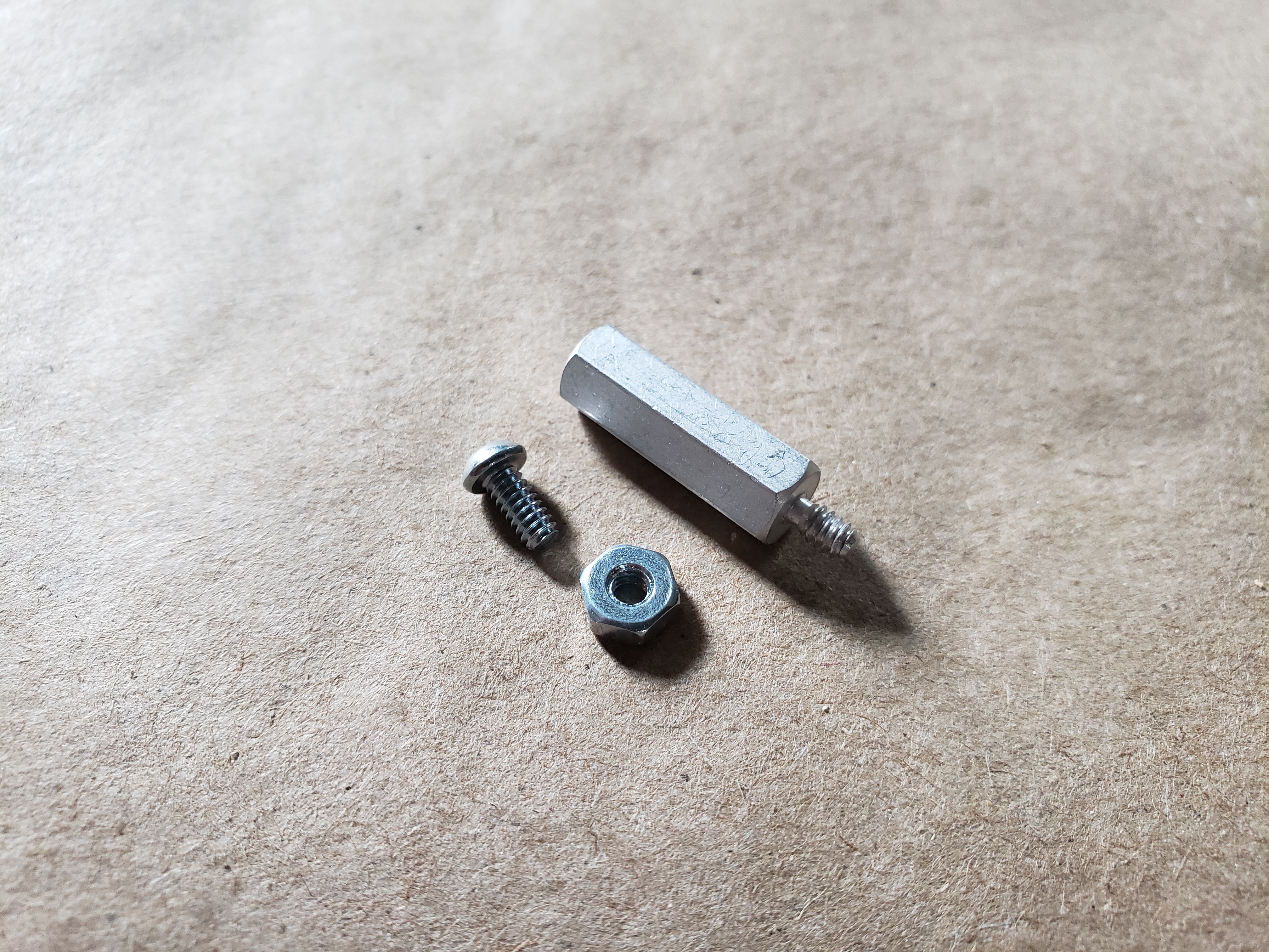
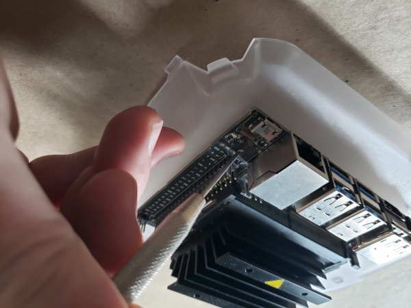
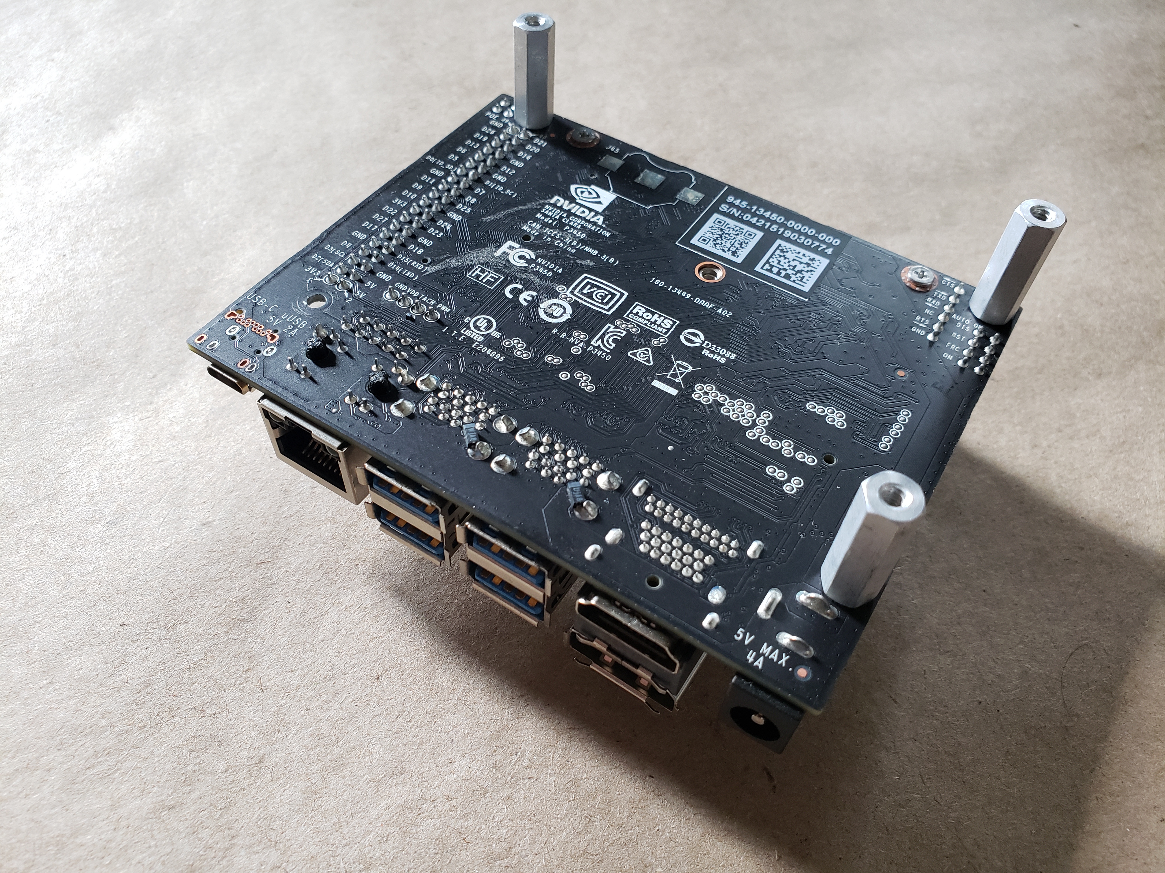
I used the aluminum standoffs from the Autonomous RVR Topper Kit as they give enough height to slide the battery bank under the Developer Kit.
My first inclination was to use a nut from the bottom of the topper plate and use screws from the top so that I could quickly and efficiently remove the Jetson Nano from the topper place without accessing the bottom, but the thickness of the topper plate become an issue for the stud length of the standoff. Instead, I used the screws to come up from the bottom and used nuts to hold the Developer Kit down.
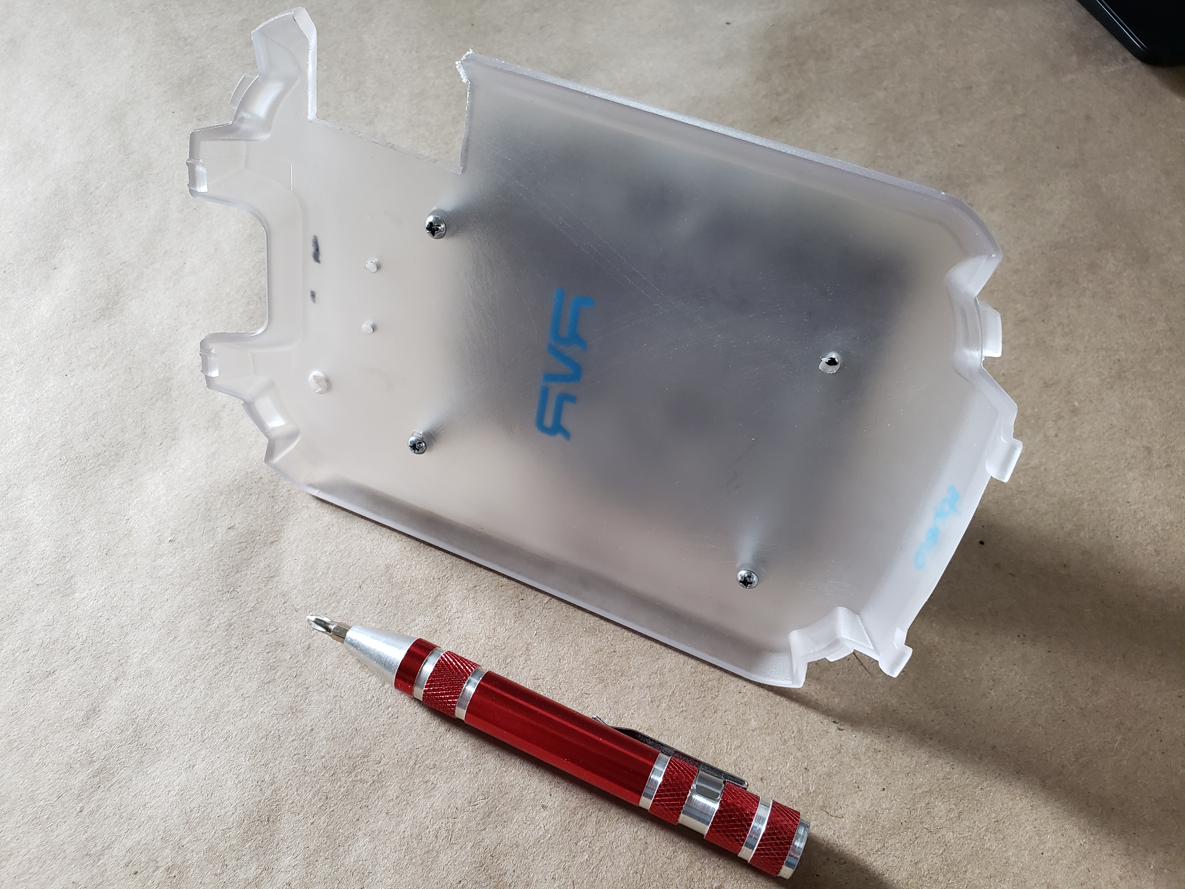
With the Dev Kit mounted to the topper plate I checked the fit with the RVR. Everything seemed to fit just fine and I took a nail file to the edges that I cut in the plate to smooth them out a bit.
Jetson Nano Peripherals
The Jetson Nano requires a few things to get up and running before we dig too deep into building up the robot and forget about them!
Micro SD Card and JetBot image
Since this is a mash-up of two kits I had the JetBot image already burned to the SD card that came with that kit. This was a nice option because the image already has the JetBot software on it and running out of the box which prints out the IP address of the bot over the OLED display and also has the drivers for the included Edimax WiFi adapter already installed.
If you are building this project from scratch I highly recommend starting with our JetBot image and burning it to an SD card. You can find our image and instructions for preparing the SD card, burning it and configuring it at the end of our JetBot Assembly Guide. You can find the Software Setup section of that guide here.
Once you have an a microSD card with the JetBot image on it, insert it into the microSD card slot on the NVIDIA Jetson Nano. The card will give a satisfying click when inserted far enough. That’s it, you are all set!
Edimax WiFi Adapter
The JetBot requires a WiFi connection so that you can communicate with it while it is free to roam/drive around untethered.
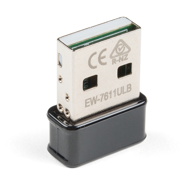
The Edimax N150 WiFi adapter is what we use in our JetBot kit and our go-to WiFi accessory for working with the NVIDIA Jetson Nano.
Installing the N150 is as simple as inserting it into an open USB port on the Jetson Nano. Software setup is a breeze if you are using our JetBot microSD card image. It should work out of the box.
If you are building this project from scratch you will need to install the drivers for the WiFi adapter. You can find our tutorial for how to do that here:
Adding WiFi to the NVIDIA Jetson
April 23, 2020
SparkFun Hardware
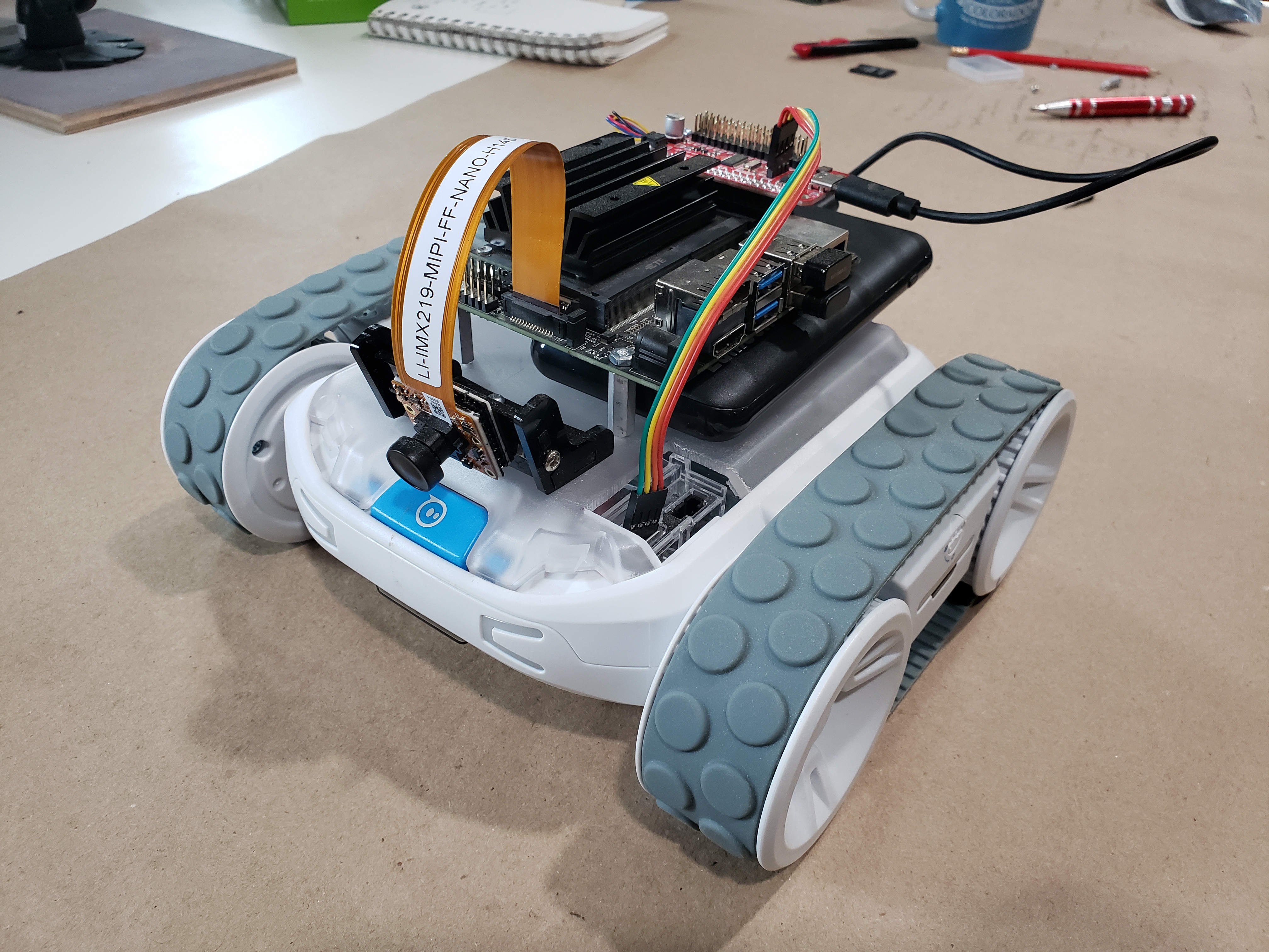
With the Jetson Nano Dev kit mounted to the topper plate it was now time to start to build out the rest of my system's hardware. I used a combination of SparkFun hardware from both the JetBot as well as the Autonomous Kit for the RVR.
SparkFun Servo pHAT
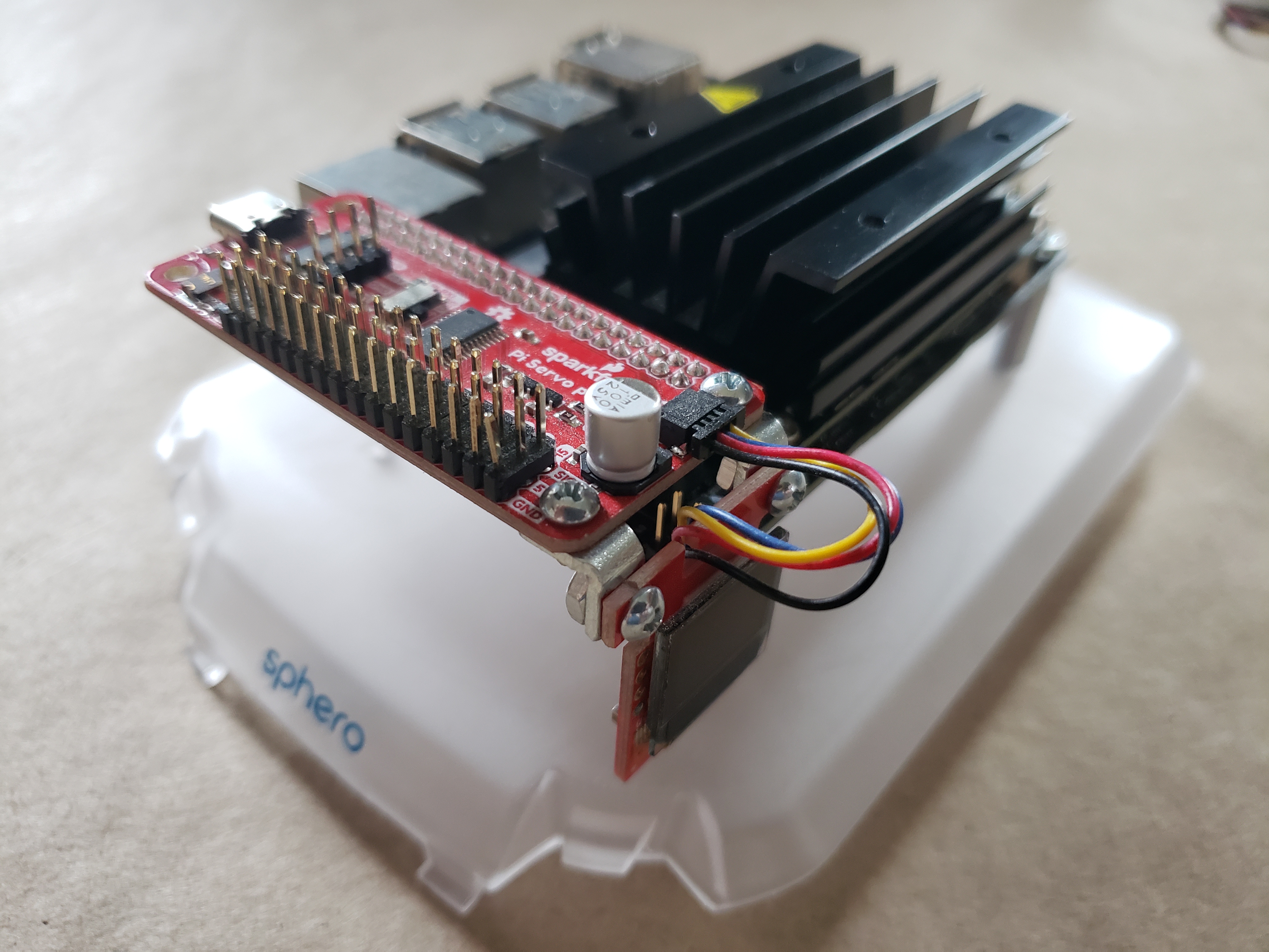
The crux of this project is the SparkFun Servo pHAT.
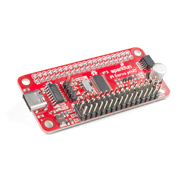
This pHAT enables a number of things for this project. Probably the most important is that it gets us access to a 4 pin UART connection to enable clean and straightforward wiring for the UART communication wires between the Nano and the RVR.
It is also how we are going to provide power to the Jetson Nano through the USB-C connector as well as other peripheral hardware using the Qwiic connector on it as well.
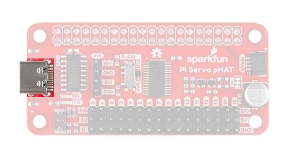
We use this connector for power rather than the USB or barrel jack power supply on the Jetson Nano Developer Kit so that we have access to raw power for both the Qwiic boards but more importantly any other hardware we want to hook up such as servo motors, etc.
Micro OLED Breakout (Qwiic)
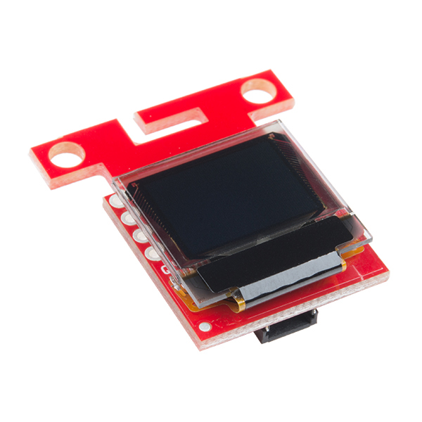
If you own a JetBot kit, you know that the OLED display is a really handy part of the bot. The JetBot uses the OLED to print out important information about the JetBot's network connection, CPU and memory usage as well as its IP address. This is really handy when you need to access and program your robot through the Jupyter Notebooks application which you can access via a browser pointed at the JetBot's IP address. More on that in the programming tutorial!
Mounting the display was a tricky problem for this project, but with some ingenuity and a few 90 degree mounting brackets I found a good place to put it that is out of the way, but still accessible and visible.
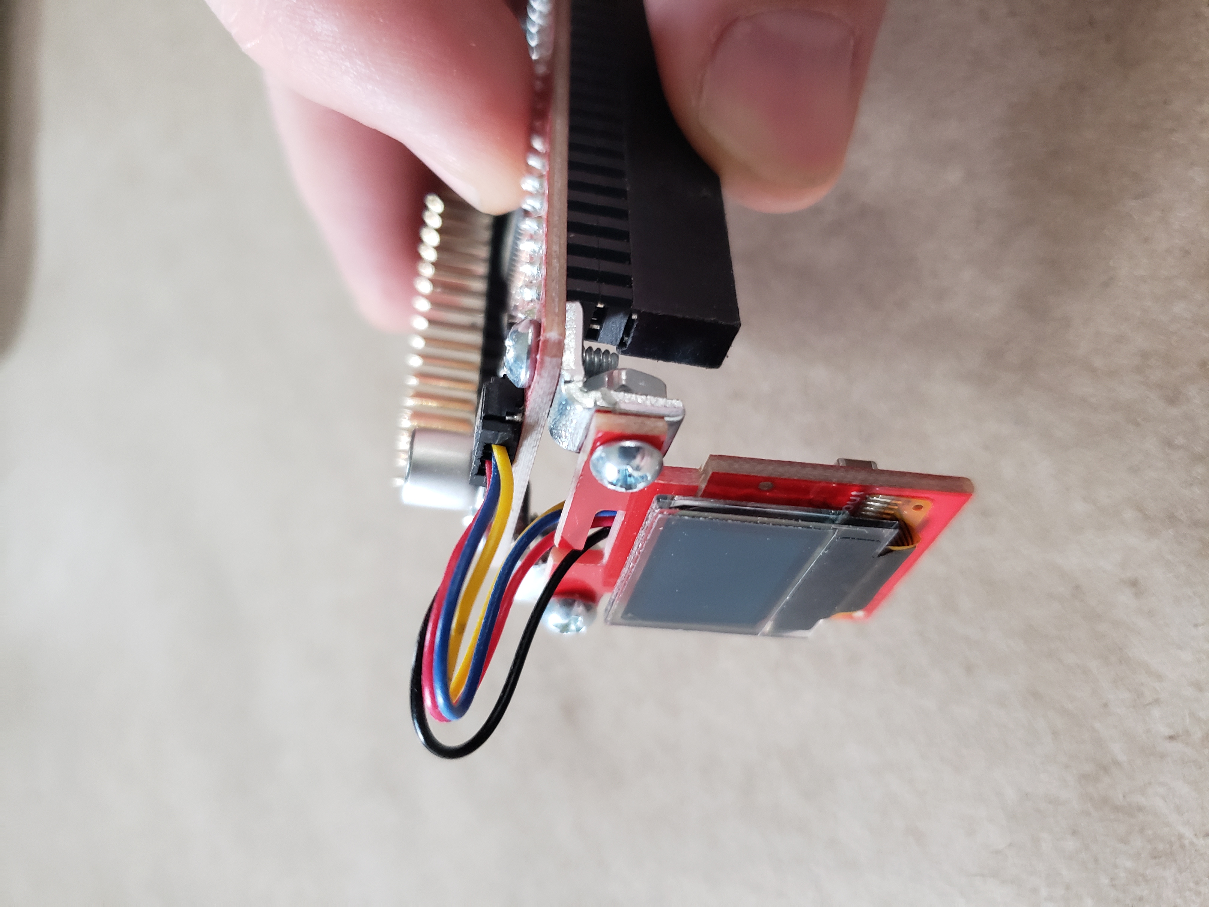
These 90 degree brackets are one thing that I used that was not included in one of the two kits I started with.
With the display mounted to the Servo pHAT and connected to it via a Qwiic cable I placed the pHAT on the Jetson Nano Dev kit as shown.
Camera and Camera Mount
The camera mounting portion of this project was by far the most DIY modification and has been iterated on over time as JetBot itself has been changed up over the course of the year.
Camera Mount
When this project initially started, the camera mount that came with our original JetBot was made of clear acrylic and wouldn't work with how things were laid out on the RVR.

For the machine learning aspect of JetBot to work properly the camera needed to be at a specific height, distance from the front axle of the drive wheels as well as tilt angle. So, with that information in hand I built my own camera mount from a bit of scrap MDF board and hot glue. This solution worked out well, but it does have a few downsides, one of them being that I used glue which doesn’t bode well when I need to remove or replace parts. But, for initial ideation it worked perfectly.
Camera Mount Revision
The advent of JetBot 2.0 and the change in chassis and how we mount the camera on it gave me an opportunity to revise my own camera mount. (Read as "a better mount to modify for our own use!")
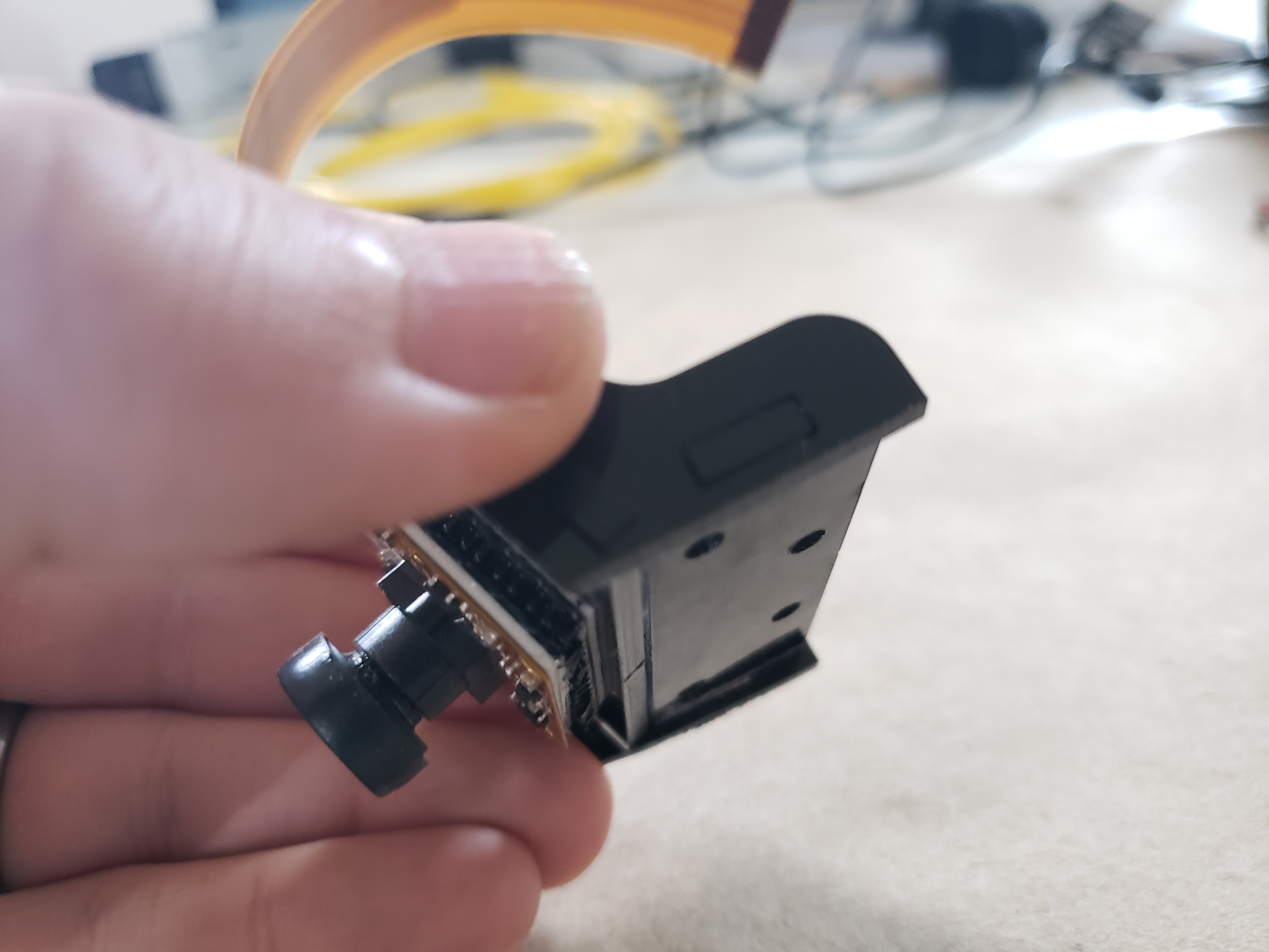
With the new camera mount in hand I used my disk sander to remove the tabs on the bottom of the acrylic mount so that it would sit relatively flat on the RVR.
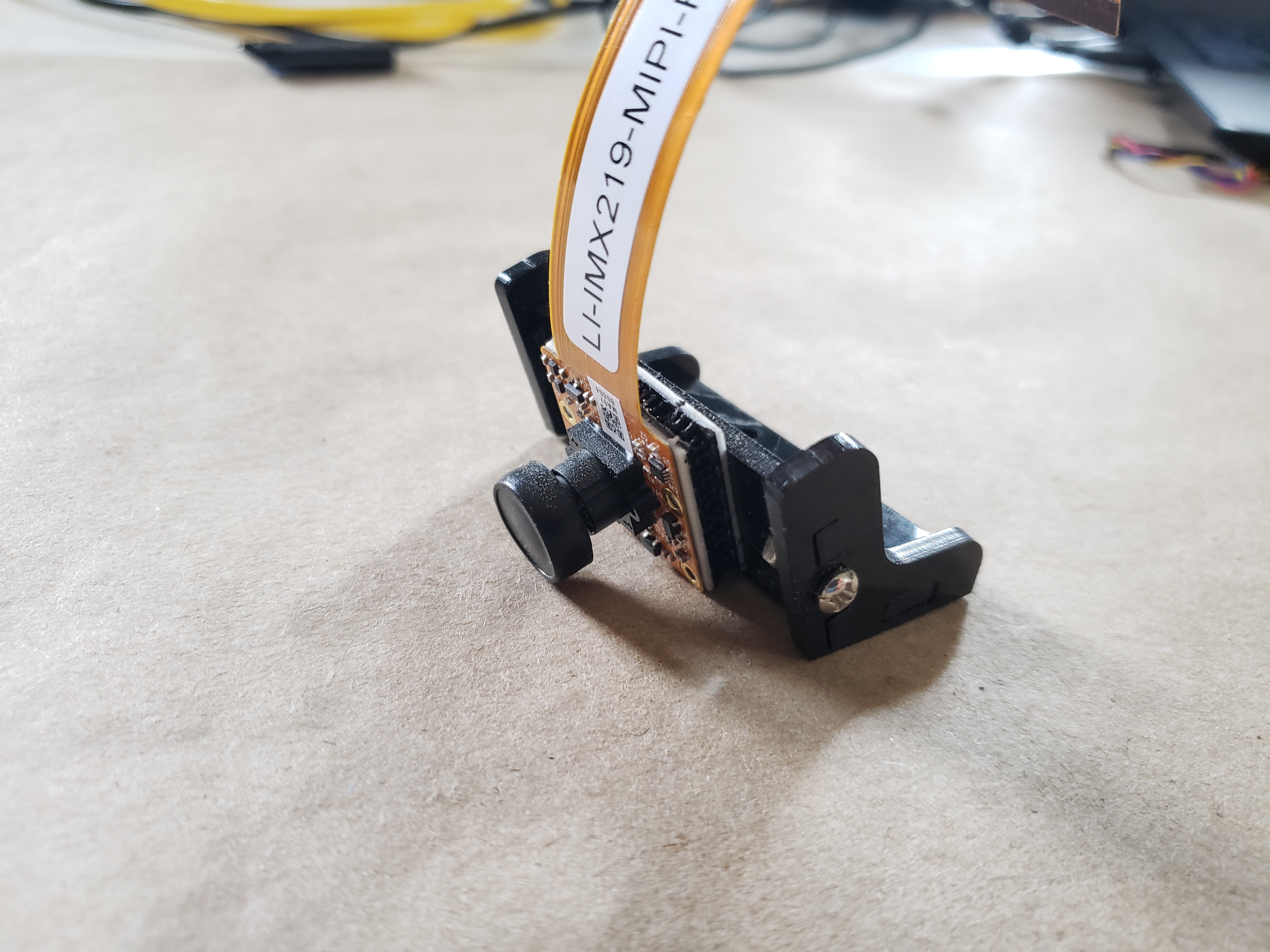
I positioned as accurately as it could be compared to the old DIY mount and a few reference marks were made before removing it. I also swapped out the plastic screw and nut that normally mount the camera to the bracket for a bit of 3M Dual Lock so that I could reposition the camera if needed. I drilled holes in the topper plate to run screws through and secure the new mount. Only use two of the holes as it would be more than enough for this light camera. I chose the two furthest back but feel free to use whichever holes work best for your robot.
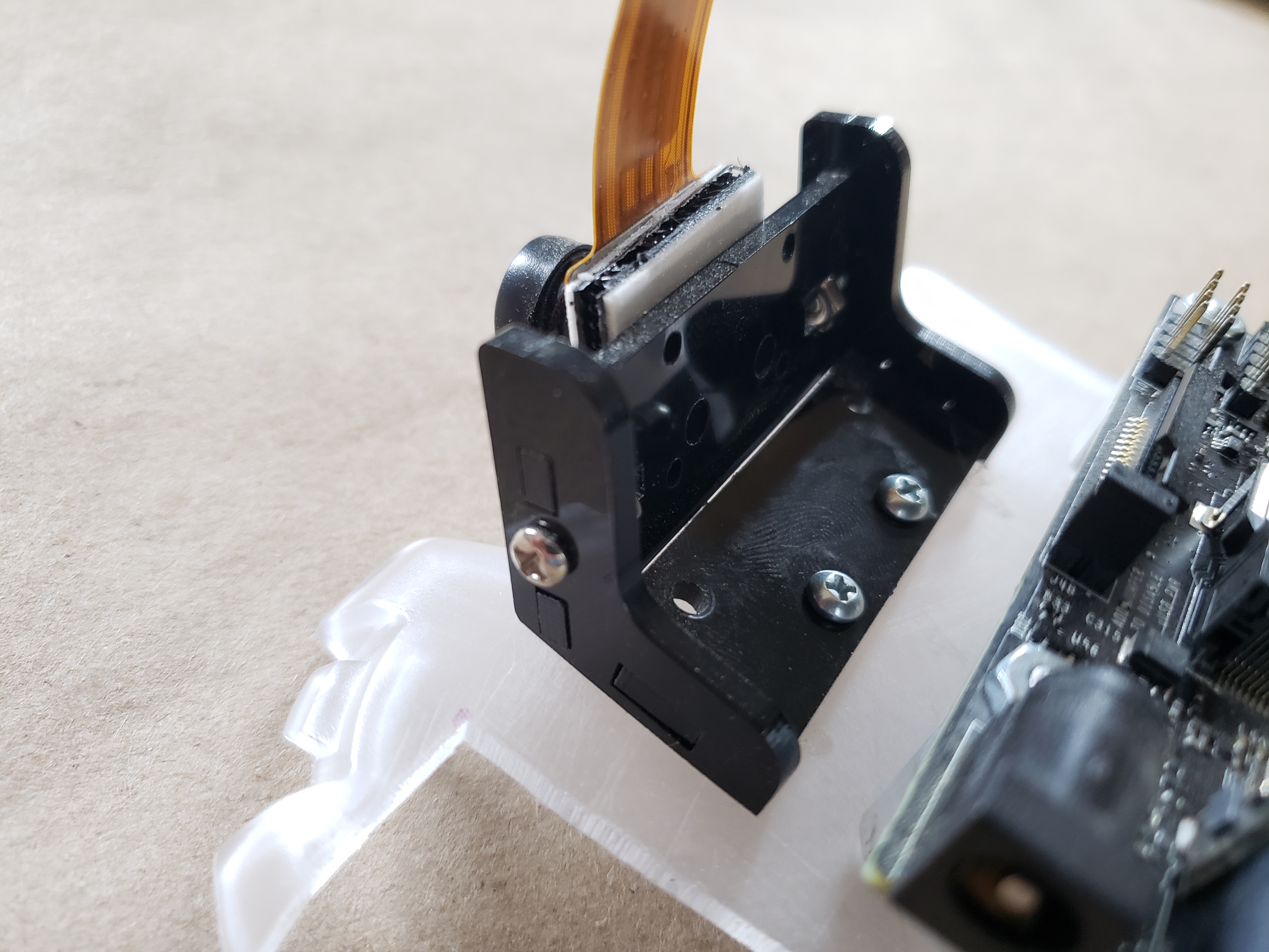
Camera Hookup
With the mounting bracket assembled and mounted to the topper plate I added the camera to the mounting bracket using some 3M Dual Lock rather than the plastic screws as shown in the JetBot assembly guide. The idea behind this would be to make it more adjustable if needed since it will be on the RVR chassis and not as optimally positioned as a chassis designed for it.

With the camera mounted, hook up is rather straightforward using the camera cable connector on the development kit carrier board. If you are using the original carrier board, you only have one choice in terms of camera connector.
Final Wiring
With the hardware assembly for the most part complete. It is now time to mount the plate with our hardware to the RVR and to do some final wiring, which is rather minimal!
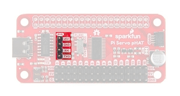
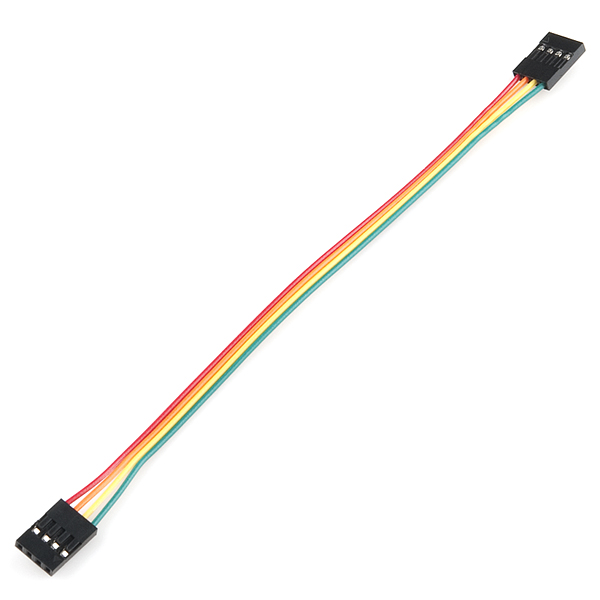
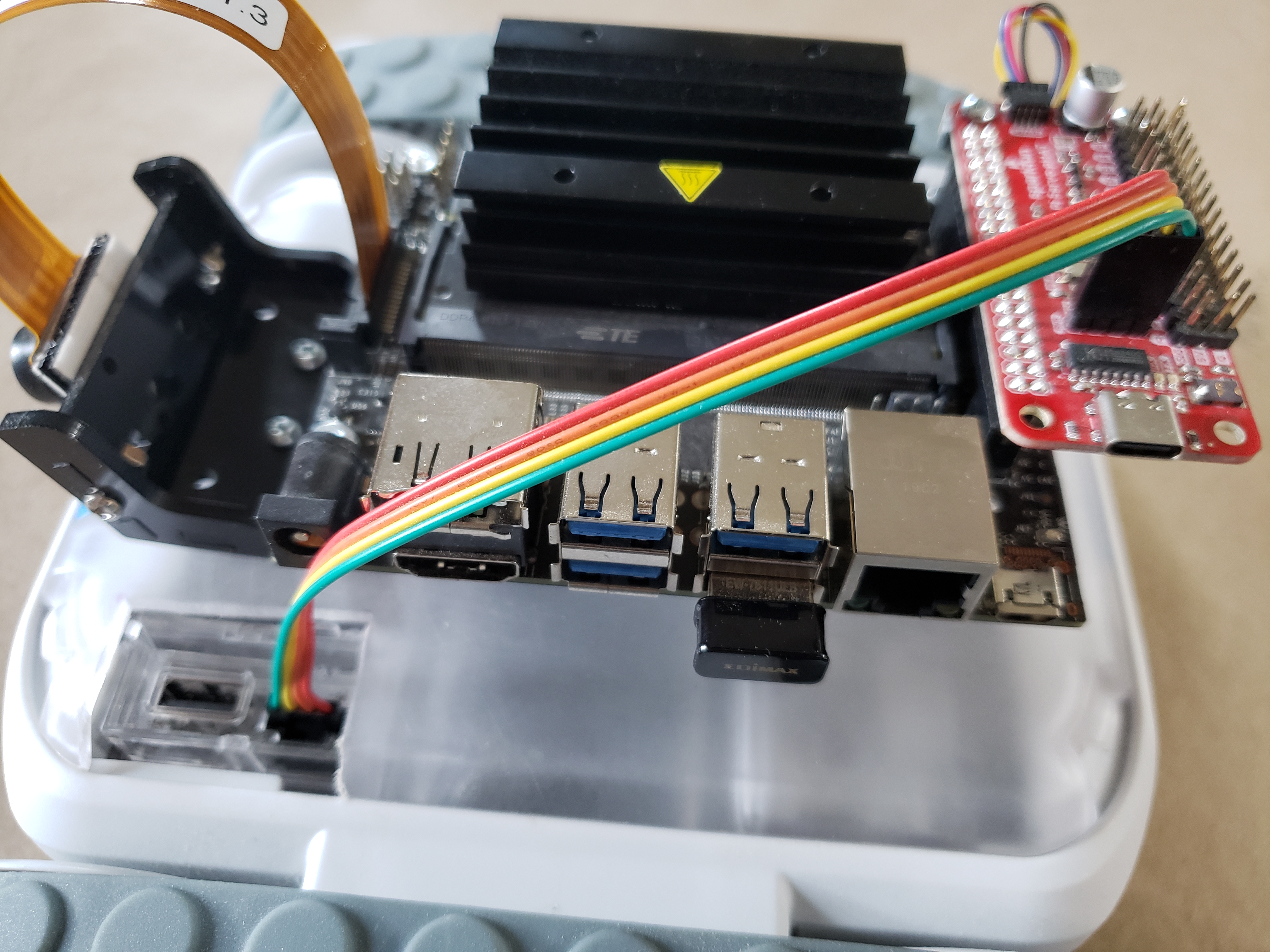
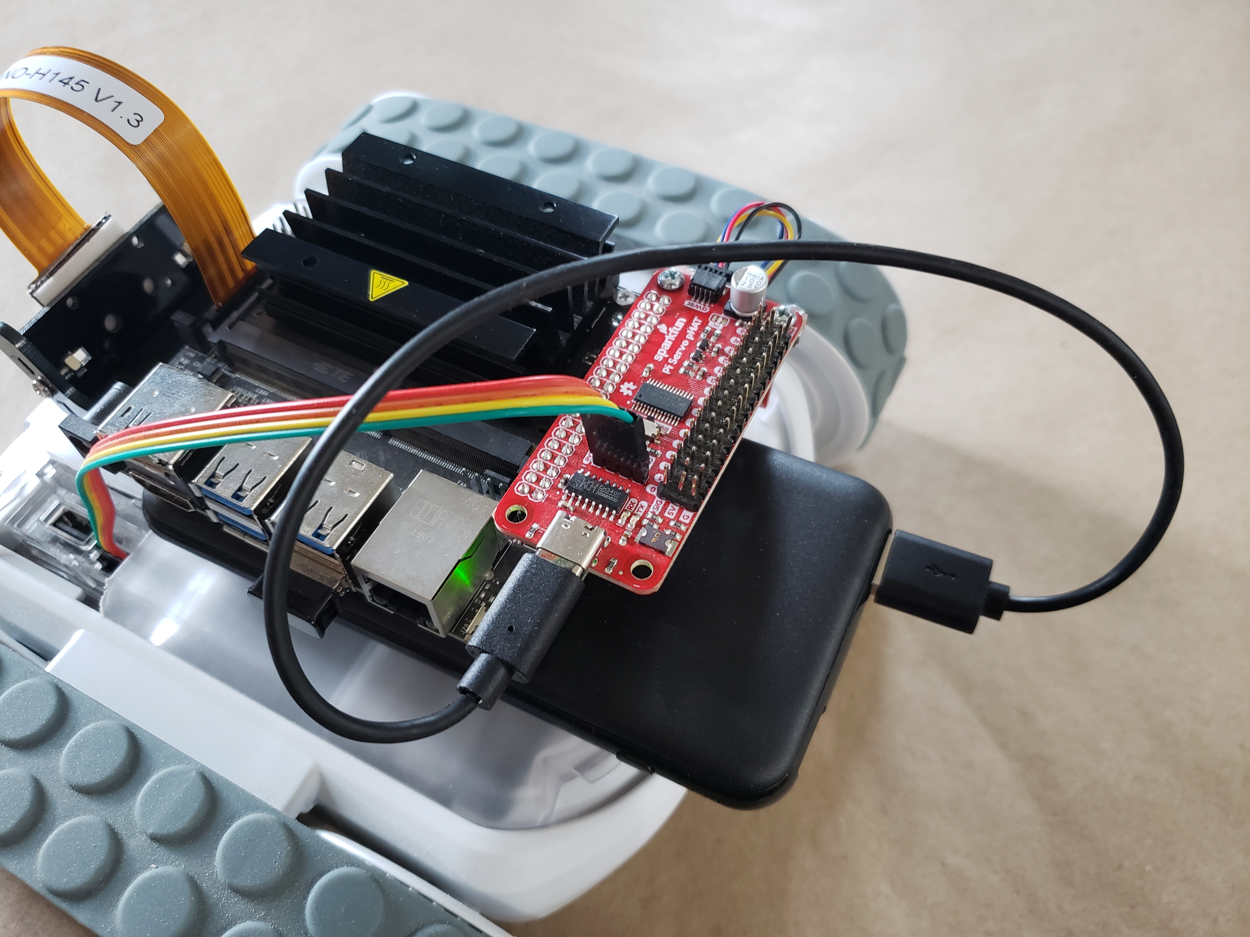
4 Pin UART Cable
The Jetson Nano communicates with the Sphero RVR via UART and a raw UART connection on the RVR next to the USB port. This four pin connector uses a 4 wire female wiring harness to connect it to the “RVR” connector on the Servo pHAT.
When connecting the pHAT to the RVR take note of the orientation of the connections. On the RVR, the UART Rx and Tx pins are oriented towards the “front” of the RVR with power (5V and GND) towards the back. You should insert the harness with the green wire pointed “forward”

The pHAT is the opposite of the RVR connector. The Rx and Tx connections are “forward” in this current configuration, so the harness should be connected to the pHAT with the red wire oriented “forward”.
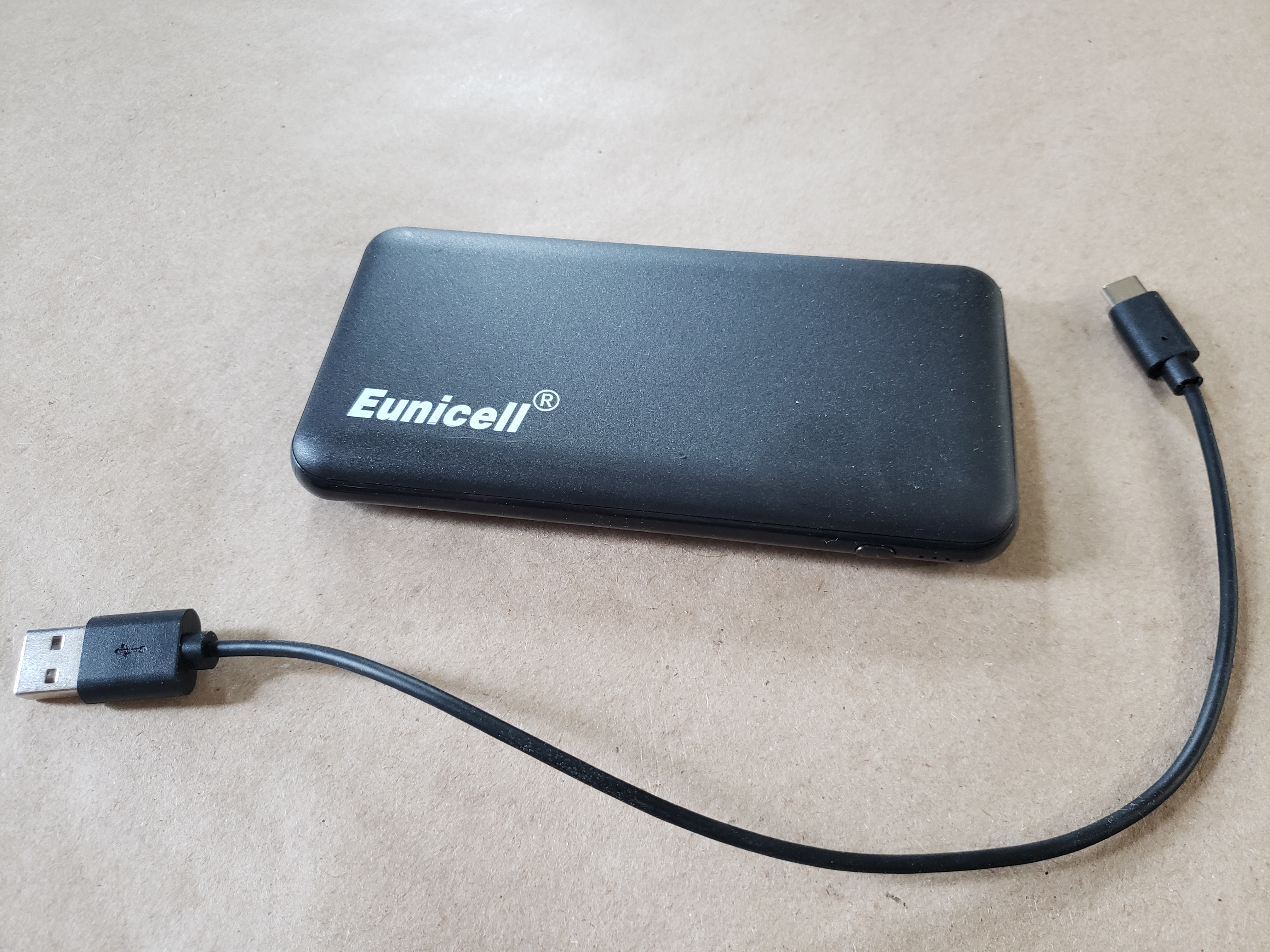
USB Battery Bank
The last thing to do before hardware assembly is completely finished is adding the USB battery bank and powering the Jetson Nano. The project uses the USB battery bank we use in our JetBot kit. It is perfect for powering the Jetson Nano and the peripherals while the RVR is powered through its own battery.
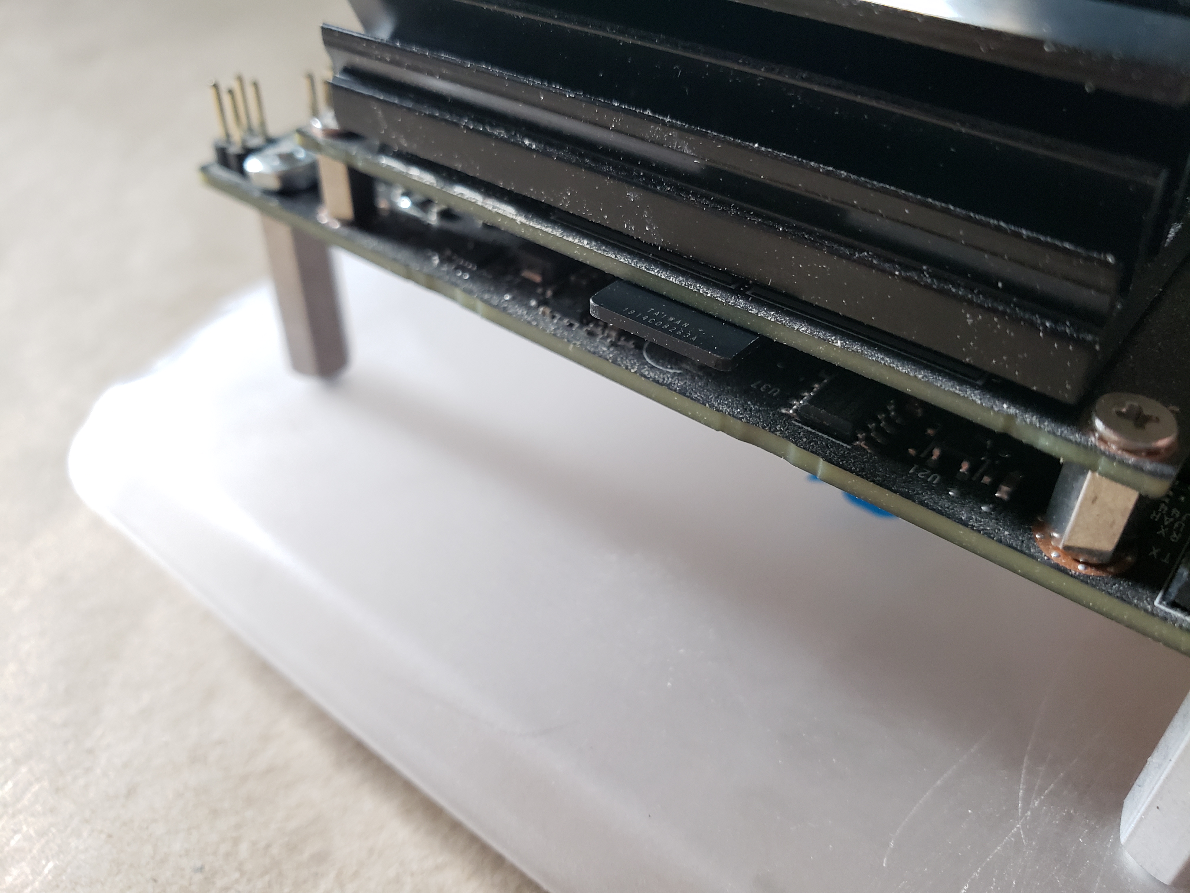
Originally we wanted to mount the Jetson on four standoffs rather than three (You can probably see 4 holes in close-up shots of the topper plate), but once we went to fit the battery on the bot it would not fit between the standoffs. To fix this we removed one so the battery would fit in the proper orientation.
The standoffs give just enough room for the battery to slide under the carrier board of the Jetson Nano. It should be snug enough that you don't need anything to keep it in place, but if you feel that you do, I highly recommend using 3M Dual Lock (we provide you with a length in our JetBot kit) or even a bit of two sided tape for just a bit of extra friction to keep it in place.
With the battery in place add a USB-C cable from the battery pack to the USB-C port on the SparkFun Servo pHAT. If you are using the battery pack from the JetBot Kit, connect your USB cable to the orange (3A) USB port. The Jetson Nano should power up as soon as you do.
In Closing and Next Steps
With that, the basic structure of your NVIDIA Jetson Nano powered Sphero RVR is ready for software setup and programming.

As we alluded to throughout this tutorial this is just the start for this robot! We wanted to give you something to start with, and be able to expand on that by adding more sensors, servo motors, etc. The expansion of this project would be a breeze using Qwiic as well as our ever growing Python libraries for our Qwiic lineup. Now, to start programming we need to get some software up and running on the Nano!
Check out the following tutorial for part 2!