LED Light Bar Hookup
 jimblom
Hardware Overview
A glance at the LED Bars will reveal that there's not a whole lot required to interface with them. There are two pairs of wire pigtails coming off the sides, labeled '+' and '-'. The darker-gray wire connects to the '+' pin, and the white wire connects to '-' on both sides.
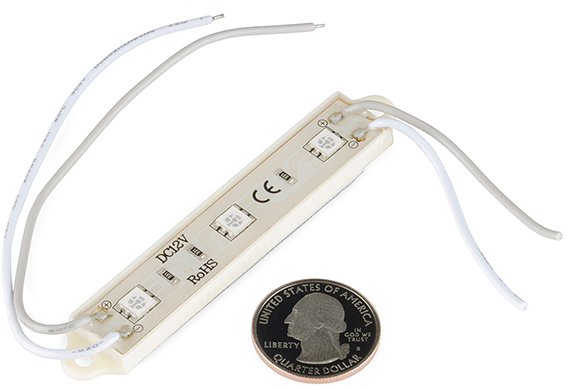
These wires supply power directly to the LEDs. A nominal voltage of 12V should be applied to these wires. A lower voltage will work (to a point) but result in dimmer LEDs. Either of the wire pairs can be used to supply power to the LED, and the unused pair can either be trimmed or connected to another LED bar.
The bars themselves measure about 3 inches across and half an inch wide. Each has three super bright SMD LEDs, which are spaced by about 1.07".
For mounting purposes there are drill holes on either side of the board, and a peel-away sticky foam on the backside.
LED Characteristics
The "nominal" voltage for these LED Bars is 12V. "Nominal" as in that's what's recommended by the manufacturer. They will work at lower voltages, although that'll mean sacrificing some brightness.
The table below shows some of the characteristics for each of the LED bar colors. These are values we found while testing the bars out. The minimum voltage was the lowest voltage where the LEDs were at recognizably lit up, although very dim. We recommend that you at least give the LEDs around 7V. The higher the voltage, the brighter your LED will be.
| Color | Minimum voltage | Current @ 7V | Current @ 9V | Current @ 12V |
|---|---|---|---|---|
| White | 4.84 V | 8.35 mA | 25.8 mA | 55.2 mA |
| Red | 2.8 V | 13 mA | 29.8 mA | 54.0 mA |
As far as current pull goes, both LED colors consume about the same when powered from between 9 and 12V, up to about 55mA when powered at the nominal voltage.
Reverse Engineering the Light Bar Circuit
Looking at the visible components on the bars, it's apparent that there's not a lot to them. Three six-pin, SMD LEDs, and an equal number of resistors. We can easily reverse-engineer this circuit to find out exactly how these things work.
Each SMD LED is actually a collection of three equal LEDs. The LED bar's PCB is set up to string those LEDs in series, with the resistor in-line to limit current. The values of the resistors depend on the color of the Bar. The red bar, for example uses 330Ω and the white bar uses 150Ω resistors.
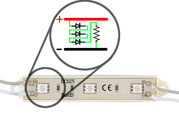
Connect three of those circuits in parallel an you have your LED bar!