Light-Seeking Robot
 Shawn Hymel
Introduction
Euglena is a genus of single-celled organisms that live in bodies of fresh and salt water. Most species of Euglena have chloroplasts that are used for photosynthesis, much like plants. Additionally, most contain a single photoreceptor and eyespot, allowing the Euglena to track and move toward light sources. To learn more about Euglena, see this Wikipedia page. You can also see hundreds of Euglenas swimming around in this video.
To emulate Euglena behavior, we're going to make a light-seeking robot that moves toward areas of bright light. The SIK v4.0 only comes with one photocell (light sensor), which means that we will need to have our robotic "organism" turn left and right in order to detect the direction of brightest light.
Required Materials
You can complete this project with parts from the SparkFun Inventor's Kit v4.0. Specifically, you will need:
You will also need (included in the SIK v4.0):
- Binder clip
- Velcro or Dual Lock fastener
Tools Needed:
- Scissors
- Screwdriver (included in the SIK v4.0)
Suggested Reading
If you aren't familiar with the following concepts, we recommend checking out these tutorials before continuing:
What is an Arduino?
Installing Arduino IDE
TB6612FNG Hookup Guide
Hardware Assembly
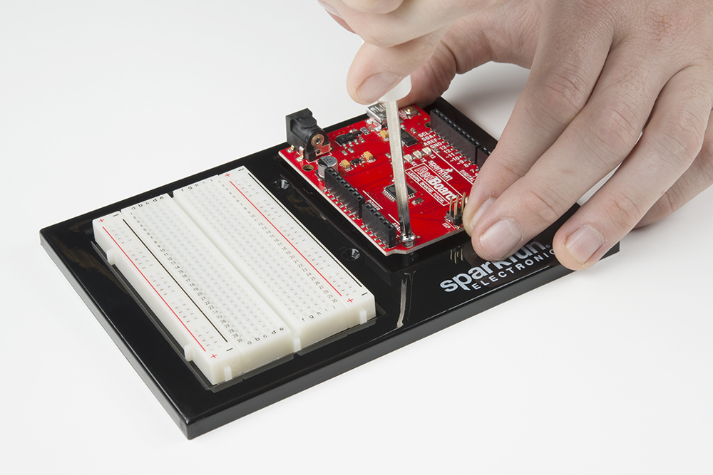
To begin, make sure that your breadboard and Arduino are secured to the baseplate. Complete instructions for attaching both can be found here.
Using scissors, cut three strips of Dual Lock that are 1.25 inches (3.2cm) long and 1 inch (2.5cm) wide. Remove the adhesive backing, and attach two pieces to the corners under the baseplate and a third in the center.
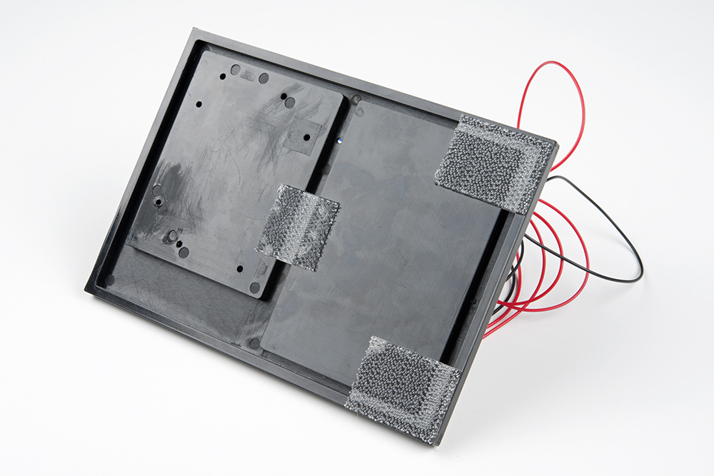
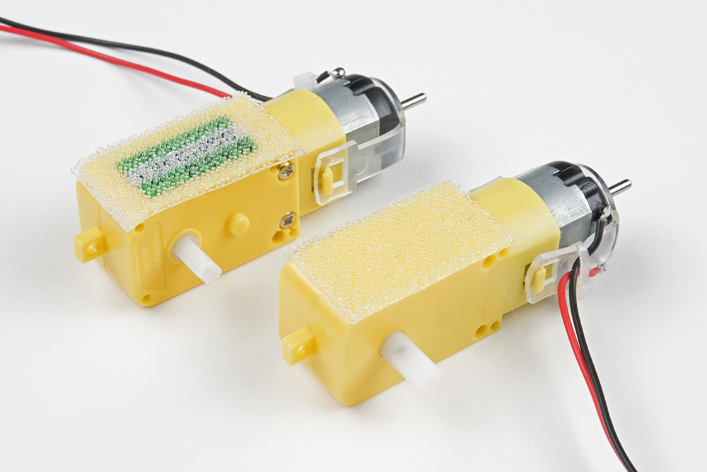
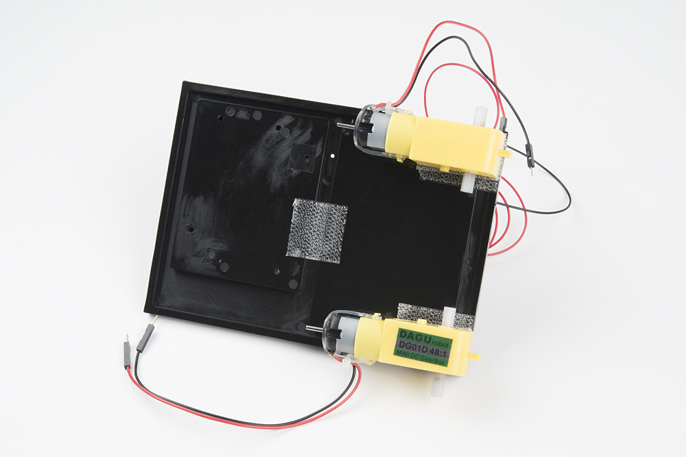
Cut two more strips that are 1.25 inches (3.175cm) long and ¾ inch (1.9cm) wide. Remove the adhesive backing, and attach the strips to the two motors. Be sure that your motors are mirror images of each other when you attach the Dual Lock.
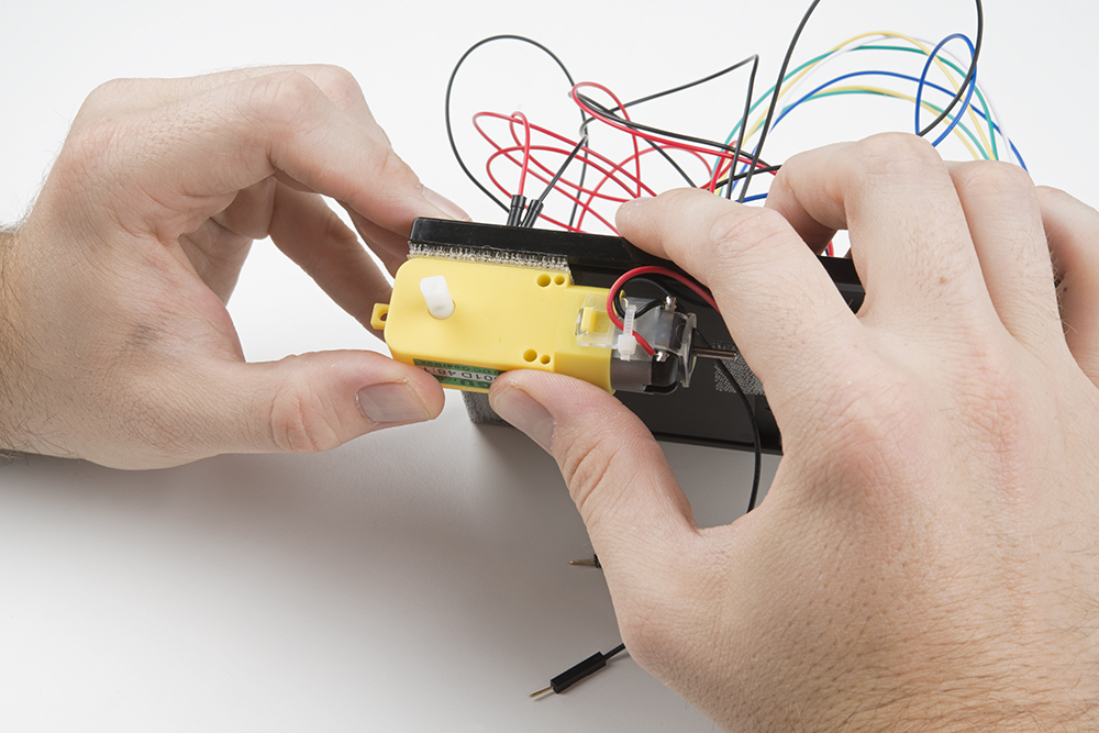
Press the motors to the baseplate, connecting the two Dual Lock surfaces. Try to get the motors as straight as possible so your robot will drive straight.
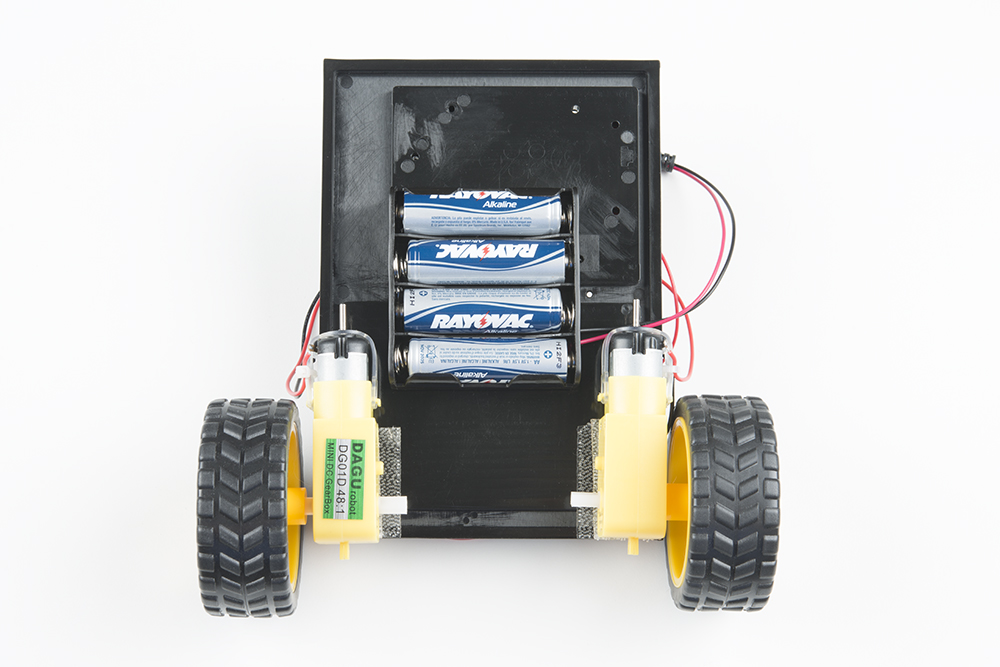
The bottom of your baseplate should look like the image below. Remember that the two motors should be mirror images of each other.
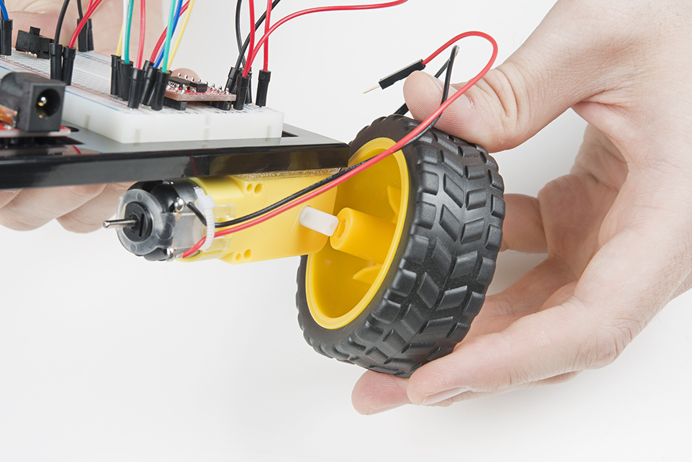
Attach the wheels by sliding them onto the plastic shafts on the gearmotor. The shaft is flat on one side, as is the wheel coupler. Align the two, and then press to fit the wheel onto the shaft.
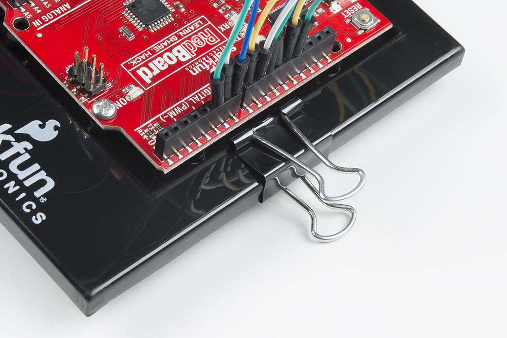
Clip the binder clip onto the back end of the robot. This will act as a caster as the robot drives around.
Cut a piece of Dual Lock that is about 1.25 inch x 1 inch (3.2cm x 2.5cm). Remove the adhesive backing and attach it to the back of the battery holder.
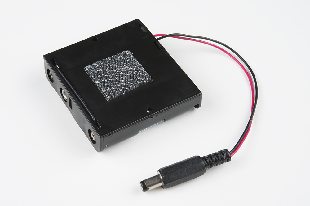
Press the battery holder to the baseplate so that the two pieces of Dual Lock snap together. Insert the batteries into the holder if you have not done so already. Remember that batteries are polarized and can only go in one way.
Circuit Diagram
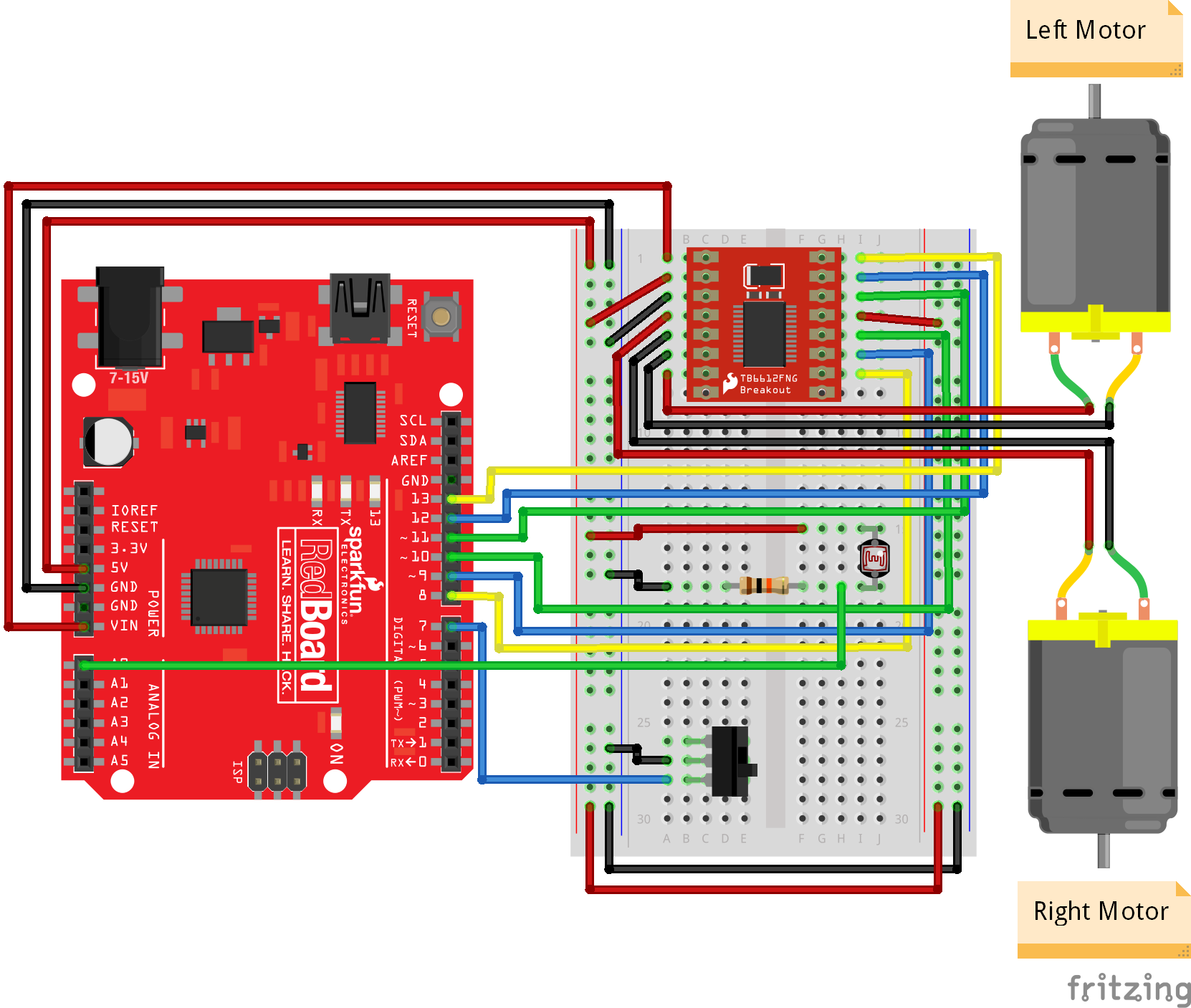
Using jumper wires, connect the components as shown in the diagram below.
Programming
Note: This example assumes you are using the latest version of the Arduino IDE on your desktop. If this is your first time using Arduino, please review our tutorial on installing the Arduino IDE.
Copy and paste the following code in the Arduino IDE. Click Upload and see what happens!
language:c
/**
 * Light Seeking Robot
 * Date: November 9, 2017
 * Author: Shawn Hymel (SparkFun Electronics)
 *
 * 2-wheeled robot moves toward the brightest light by first
 * checking left, right, and center.
 *
 * Parts for this project can be found in the SparkFun
 * Inventor's Kit v4.0: https://www.sparkfun.com/products/14265
 *
 * This sketch was written by SparkFun Electronics, with lots of
 * help from the Arduino community. This code is completely free
 * for any use.
 */

// Pins
const int PWMB = 8;
const int BIN2 = 9;
const int BIN1 = 10;
const int AIN1 = 11;
const int AIN2 = 12;
const int PWMA = 13;
const int SW_PIN = 7;     // Switch to turn the motors on and off
const int LIGHT_PIN = A0; // Photocell

// Constants
const int SEARCH_DRIVE_TIME = 200;  // Time to run one motor while searching
const int TURN_DRIVE_TIME = 200;    // Time to turn in a direction
const int MOVE_DRIVE_TIME = 300;   // Time to drive in a direction
const int STOP_DRIVE_TIME = 200;    // Time to stop after moving
const int NUM_LIGHT_LEVELS = 3;

void setup() {

  // Set switch pin
  pinMode(SW_PIN, INPUT_PULLUP);

  // Set the motor control pins as outputs
  pinMode(AIN1, OUTPUT);
  pinMode(AIN2, OUTPUT);
  pinMode(PWMA, OUTPUT);
  pinMode(BIN1, OUTPUT);
  pinMode(BIN2, OUTPUT);
  pinMode(PWMB, OUTPUT);

  // Initialize Serial comms
  Serial.begin(9600);
  Serial.println("Feed me photons!");
}

void loop() {

  // Store light levels as array [left, center, right]
  int light_levels[NUM_LIGHT_LEVELS];

  // If switch is flipped, search for light
  if(digitalRead(SW_PIN) == LOW){

    // Record light value to the left
    drive(0, 255);
    delay(SEARCH_DRIVE_TIME);
    drive(0, 0);
    delay(STOP_DRIVE_TIME);
    light_levels[0] = analogRead(LIGHT_PIN);
    drive(0, -255);
    delay(SEARCH_DRIVE_TIME);
    drive(0, 0);
    delay(STOP_DRIVE_TIME);

    // Record light value to the right
    drive(255, 0);
    delay(SEARCH_DRIVE_TIME);
    drive(0, 0);
    delay(STOP_DRIVE_TIME);
    light_levels[2] = analogRead(LIGHT_PIN);
    drive(-255, 0);
    delay(SEARCH_DRIVE_TIME);
    drive(0, 0);
    delay(STOP_DRIVE_TIME);

    // Record light value in the center
    light_levels[1] = analogRead(LIGHT_PIN);

    // Find direction of max light
    int max_light = 0;
    int max_light_index = 0;
    for ( int i = 0; i < NUM_LIGHT_LEVELS; i++ ) {
      if ( light_levels[i] > max_light ) {
        max_light = light_levels[i];
        max_light_index = i;
      }
      Serial.print(light_levels[i]);
      Serial.print(" ");
    }
    Serial.println();
    Serial.print("Max light: ");
    Serial.println(max_light_index);

    // Move in the direction of max light
    if ( max_light_index == 0 ) {
      Serial.println("Chasing light to the left");
      drive(-100, 255);
      delay(TURN_DRIVE_TIME);
      drive(255, 255);
      delay(MOVE_DRIVE_TIME);
      drive(0, 0);
      delay(STOP_DRIVE_TIME);
    } else if ( max_light_index == 1 ) {
      Serial.println("Chasing light straight ahead");
      drive(255, 255);
      delay(MOVE_DRIVE_TIME);
      drive(0, 0);
      delay(STOP_DRIVE_TIME);
    } else {
      Serial.println("Chasing light to the right");
      drive(255, -100);
      delay(TURN_DRIVE_TIME);
      drive(255, 255);
      delay(MOVE_DRIVE_TIME);
      drive(0, 0);
      delay(STOP_DRIVE_TIME);
    }

  // If switch is not flipped, do nothing
  } else {
    drive(0, 0);
  }
}

void rightMotor(int motorSpeed)
{

  // If speed is positive, run the motor forward
  if (motorSpeed > 0) {
    digitalWrite(AIN1, HIGH);
    digitalWrite(AIN2, LOW);

  // If it's negative, run the motor backward
  } else if (motorSpeed < 0) {
    digitalWrite(AIN1, LOW);
    digitalWrite(AIN2, HIGH);

  // If it's 0, brake the motor
  } else {
    digitalWrite(AIN1, LOW);
    digitalWrite(AIN2, LOW);
  }
  analogWrite(PWMA, abs(motorSpeed));
}

void leftMotor(int motorSpeed)
{
  // If speed is positive, run the motor forward
  if (motorSpeed > 0) {
    digitalWrite(BIN1, HIGH);
    digitalWrite(BIN2, LOW);

  // If it's negative, run the motor backward
  } else if (motorSpeed < 0) {
    digitalWrite(BIN1, LOW);
    digitalWrite(BIN2, HIGH);

  // If it's 0, brake the motor
  } else {
    digitalWrite(BIN1, LOW);
    digitalWrite(BIN2, LOW);
  }
  analogWrite(PWMB, abs(motorSpeed));
}

void drive(int leftSpeed, int rightSpeed) {
  leftMotor(leftSpeed);
  rightMotor(rightSpeed);
}
What You Should See
When the switch is OFF, the robot will not move. When you turn the switch ON, the robot will turn left and right, taking light measurements at each extreme. It will also take a light measurement from the center.

The robot turns to the direction with the most light and moves forward a small amount. It then repeats the pattern of looking for light and moves toward the direction of brightest light.
Note that trying to direct the robot with a flashlight or other light source can be difficult. Reflected light from the wheels can sometimes be brighter, for instance, than reflected light on the ground. It can take some patience to get the robot to move the way you want. You can also try modifying the code to make it faster at taking three measurements (by spinning the wheels more quickly or not turning as far to measure) or to take more than three measurements at a time.
Resources and Going Further
The code and circuit diagram for the Light-Seeking Robot project can be found on GitHub.
Next Steps
Right now, your robot has only one sensor and performs a very simple search-decide-move loop. If you wanted to make your mechanical and electrical "organism" more robust and smarter, you could use additional sensors, such as an Ultrasonic Distance Sensor to determine if the robot is about to hit an object.
Additionally, you could give your robot very simple artificial intelligence (AI) by using algorithms like Q-Learning so that it learns how to respond to various sensor inputs.
Need some inspiration for your next project? Check out some of these related tutorials: