LilyPad Development Board Activity Guide
 Gella
Gella 
Before You Begin
Note: This guide assumes you are using the latest version of the Arduino IDE on your desktop. If this is your first time using Arduino, please review our tutorial on installing the Arduino IDE. If you have not previously installed an Arduino library, please check out our installation guide.
Installing Arduino IDE
March 26, 2013
Download LilyPad Development Board Example Code
To follow along with the activities in this guide, download the LilyPad Development Board Example Code. Click the following link to download the code:
Place the LilyPadDevelopmentBoard_ActivityGuide folder in the Arduino IDE examples directory:
- Windows: drag the
LilyPadDevelopmentBoard_ActivityGuidefolder intoC:\program files\Arduino-x\examples - MacOS: Right-click on the Arduino IDE app and click "Show Package Contents...". Drag the
LilyPadDevelopmentBoard_ActivityGuidefolder intoContents/Resources/Java - Linux: see http://www.arduino.cc/playground/Learning/Linux
You can also download the code from GitHub.
Install FTDI Drivers
If you've never used a LilyPad Arduino before, you will need to install FTDI drivers. Depending on your computer’s operating system, you will need to follow specific instructions. Please go to How to Install FTDI Drivers, for specific instructions on how to install the FTDI drivers onto your computer.
USB Serial Driver Quick Install
August 31, 2017
Note that you won't have to install the FTDI drivers again, but you will need to perform the below three steps every time you want to program the board. These three steps are:
2. Select "LilyPad Arduino" from Arduino's "Board" menu.
3. Select "ATmega328" from Arduino's "Processor" menu.
4. Select the serial port the LilyPad is connected to from Arduino's "Port" menu.
Let's go over the three steps in detail:
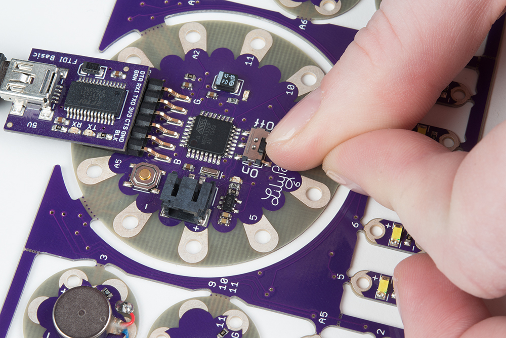
1. Connect the LilyPad Development Board to Your Computer
Place the LilyPad Development Board on a clean, non-metal work surface. Connect the LilyPad FTDI Board to the headers on the LilyPad Arduino Simple at the center of the Development Board.
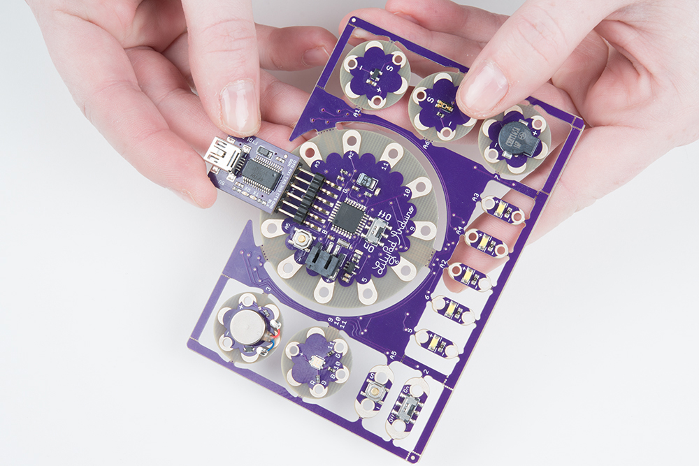
Connect the other side of the FTDI board to a mini-B USB cable.The cable can only be inserted one way, and should snap in securely.
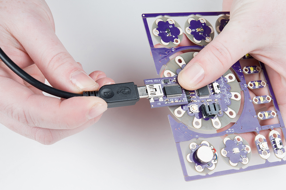
Then connect the other end of the USB cable to a USB port on your computer.
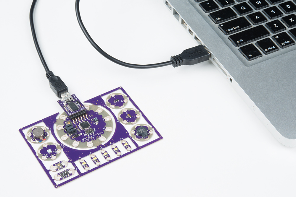
Slide the switch on the LilyPad Arduino to the ON position. You will not be able to upload code to the board if it is set to the OFF position.
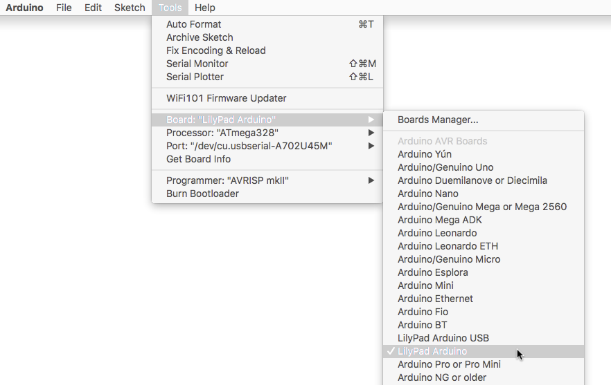
2. Select LilyPad Arduino from the Board Menu
To program the LilyPad Arduino Simple at the center of the LilyPad Development Board, open the Tools > Board list and select LilyPad Arduino. A dot (Windows) or check mark (Mac) will show next to the board in the menu when it is selected, and it will show next to Board in the Tools menu.
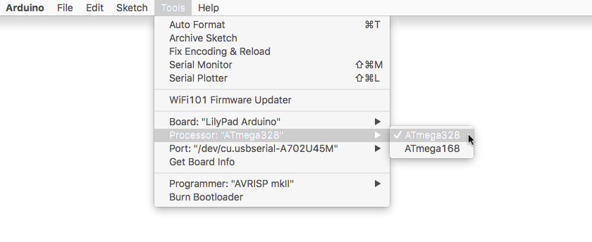
3. Select ATmega328 from the Processor Menu
After selecting the LilyPad Arduino, there will be two options available in the next menu down labeled Processor. Select ATmega328 for your LilyPad Arduino.
4. Select Port from the Port Menu
Arduino needs to know which port your LilyPad Arduino is attached to so it can program it. Whenever you plug a USB device into your computer, your computer will assign it a port number. Go to the Tools > Port menu, and select the port that has the LilyPad Arduino attached to it.
On Windows ports are listed as COM##; on a Mac or Linux machine they will be "/dev/cu.usbmodem####". Your screen may look different than the image below, depending on what operating system you are using.

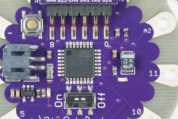
Hardware Overview
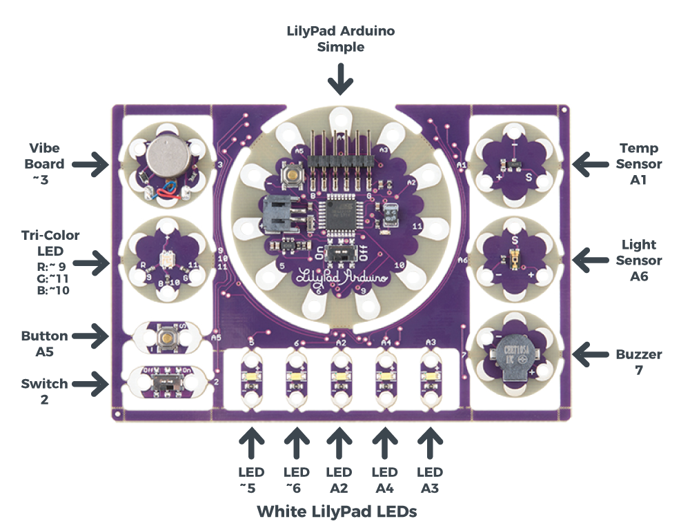
The LilyPad Development Board features twelve LilyPad components connected to a LilyPad Arduino Simple microcontroller by conductive pathways called traces. Many of these traces are hidden, but for reference, each component on the ProtoSnap has a nearby label with the number of the LilyPad Arduino Simple sew tab it is connected to. For more information on features and technical specs, please refer to the LilyPad Development Board Quickstart Guide.
What is a Program?
Programs are sets of instructions that tell a computer to do something, (also called “code” or a “sketch” in Arduino) . This could be blinking LEDs, playing sounds, making decisions based on input from sensors, or a combination of all those things.
When the computer runs a program, it will start at the first instruction, carry it out, and move on to the next one. These instructions come from a specific list of words that the computer knows. If you type in a word that the computer doesn’t know (or more likely, you misspell a word that the computer should know), you’ll get an error when you try to run your program. Don’t feel bad, this happens to everyone and is a normal part of writing programs, and we’ll provide you with some troubleshooting tips as you follow along with the activities in this guide.
In the Arduino system, you’ll write programs on your computer in a free application called the Arduino IDE (“IDE” stands for Integrated Development Environment). This is a specialized text editor with extra buttons to check and send your code to the LilyPad Arduino Simple at the center of your ProtoSnap board. We've created a set of of programming examples that you copied to a folder in the Arduino application, we’ll be using them in these activities.
What is a Microcontroller?
The LilyPad Arduino Simple at the center of your ProtoSnap board contains a tiny computer called a microcontroller. It can’t do all the things that a larger computer does, but it’s very good at running programs that control simple hardware like LEDs.
Unlike larger computers, microcontrollers don’t have keyboards and screens for input and output. Most of your input and output will happen through sew tabs; the silver petals with holes in them evenly spaced around the outer edge of all LilyPad boards. Your program can control the sew tabs. It can use them for output by turning them on and off (internally connecting them to voltage or not). It can also use them for input, measuring any voltage coming from other components. It can use this information to read buttons, switches, and various sensors, and use that information to make decisions. (We’ll explore this in future activities.)
If you look closely at the sew tabs, you’ll see that every sew tab has a label next to it. These are the names of the sew tabs, which you’ll need to know to control them from your program. You might have noticed that some of the sew tabs have an “A” as part of the label, and some include a tilde or squiggle “~”. These symbols describe special features that some of the sew tabs have. We’ll tell you about these special features in future activities.
Some of the sew tabs have a “+” or “-” next to them. You can use these sew tabs to provide power and ground to LilyPad boards connected to the LilyPad Arduino Simple.
Sew Tabs and Pins
Every microcontroller chip has electrical connections to the board that look like metal legs. These are commonly referred to as pins. Each sew tab around the outside edge of the LilyPad Arduino Simple is connected electrically to one of these pins on the microcontroller chip. In this guide, we'll be referring to sew tabs when referencing the hardware and electrical connections on your ProtoSnap and pins when talking about the code that controls electricity in or out of the tabs.