LilyPad Light Sensor V2 Hookup Guide
 Gella
Gella Introduction
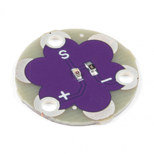
The LilyPad Light Sensor is a sewable breakout board with an ALS-PT19 light sensor on it. To use the light sensor, you will need to connect to a LilyPad Arduino or other microcontroller to read the sensor values and use them in your code.
The LilyPad Light Sensor outputs voltage between 0V and 3.3V depending on the level of ambient light shining on it. As more light is applied on the sensor, more current will flow from the board through the signal tab to the microcontroller you connect the sensor to. If the sensor receives no light, no current will flow through it. In a typical indoor lighting situation, the sensor will output around 1 to 2V.
This sensor is also used on the LilyPad ProtoSnap Plus and LilyMini ProtoSnap.
To follow along with the code examples, we recommend:
Suggested Reading
To add this sensor to a project, you should be comfortable sewing with conductive thread and uploading code to a LilyPad Arduino. Here are some tutorials to review before working with this sensor:
What is a Circuit?
Serial Terminal Basics
Getting Started with LilyPad
Attaching to a LilyPad Arduino
The LilyPad Light Sensor has three sew tabs - Power (+), Ground (-), and Signal (S). Next to each tab is a white label on the top and bottom of the board for reference. The signal tab should be connected to an analog tab (marked with an 'A') on a LilyPad Arduino.

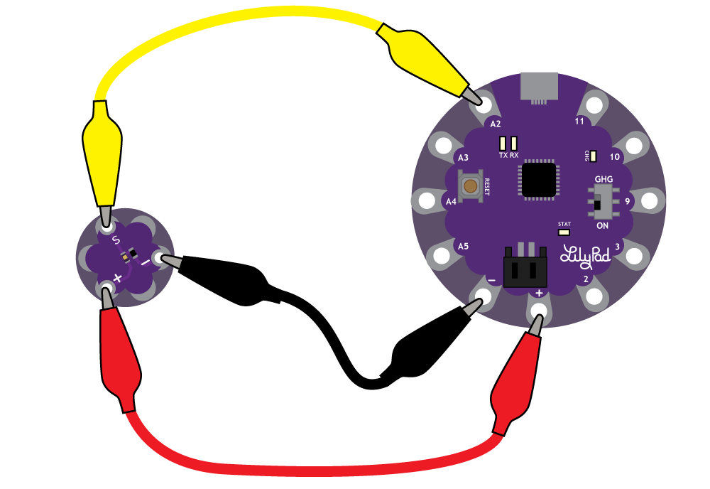
To follow along with the code examples in this tutorial, connect the light sensor to a LilyPad Arduino as shown below. Use alligator clips to temporarily connect Signal to A2 on a LilyPad Arduino, (-) to (-) on the LilyPad, and (+) to (+). When you are finished prototyping, replace the alligator clips with conductive thread traces for permanent installation in your project.
If following along with a LilyPad ProtoSnap Plus, the light sensor is pre-wired to Pin A2. The light sensor on the ProtoSnap is a slightly different version than the catalog item, but functions the same.
If following along with the LilyMini ProtoSnap,the light sensor is pre-wired to Pin 1. Again, the light sensor on the LilyMini ProtoSnap is a slightly different version than the catalog item, but functions the same.
 |
 |
| LilyPad Light Sensor location circled on a LilyPad ProtoSnap Plus board | LilyPad Light Sensor location circled on a LilyMini ProtoSnap board |
Reading Values in Serial Monitor
Note: This example assumes you are using the latest version of the Arduino IDE on your desktop. If this is your first time using Arduino, please review our tutorial on installing the Arduino IDE.
After connecting the light sensor, let's take a look at the values it reads under different lighting conditions. For this we'll use analogRead() and Serial.print().
- If prototyping with a LilyPad ProtoSnap Plus, change sensorPin to A2.
- If prototyping with a LilyMini ProtoSnap, change sensorPin to 1.
Copy the following code and upload it to your LilyPad.
language:c
/******************************************************************************

LilyPad Light Sensor Example
SparkFun Electronics

This example code reads the input from a LilyPad Light Sensor and displays in
the Serial Monitor.

Light Sensor connections:
   * S tab to A2
   * + tab to +
   * - tab to -

******************************************************************************/

// Set which pin the Signal output from the light sensor is connected to
int sensorPin = A2;
// Create a variable to hold the light reading
int lightValue;

void setup()
{
    // Set sensorPin as an INPUT
    pinMode(sensorPin, INPUT);

    // Initialize Serial, set the baud rate to 9600 bps.
    Serial.begin(9600);
}

void loop()
{

   // Get the current light level
    lightValue = analogRead(sensorPin);

   // Print some descriptive text and then the value from the sensor
    Serial.print("Light value is:");
    Serial.println(lightValue);

    // Delay so that the text doesn't scroll too fast on the Serial Monitor.
    // Adjust to a larger number for a slower scroll.
    delay(200);
}
Once your code is uploaded, open the serial terminal in the IDE and observe the output. Numbers should begin to stream by. Note how the numbers change as the ambient light changes. Use your hand to cover the sensor or a flashlight to shine more light on it. Next we'll be using these values to control behaviors in our code.
Using Values to Trigger Behaviors
Next, we'll make some decisions in the code based on the light sensor's readings. This example code creates a simple automatic night light that turns on an LED when it’s dark.
We'll use the analogRead() function to get data from the light sensor and compare it to a variable we set for darkness level. When the readings from the light sensor fall below our threshold set for dark, it will turn on the LED.
You can hook up a LilyPad LED to sew tab 5 or use the built-in LED attached to pin 13.
language:c
/******************************************************************************

LilyPad Light Sensor Trigger - Automatic Night Light
SparkFun Electronics

Adapted from Digital Sandbox Experiment 11: Automatic Night Light

This example code reads the input from a LilyPad Light Sensor compares it to
a set threshold named 'dark'. If the light reading is below the threshold,
an LED will turn on.

Light Sensor connections:
   * S tab to A2
   * + tab to +
   * - to -

Connect an LED to pin 5 or use the built-in LED on pin 13

******************************************************************************/
// The dark variable determines when we turn the LEDs on or off.
// Set higher or lower to adjust sensitivity.
const int darkLevel = 50;

// Create a variable to hold the readings from the light sensor.
int lightValue;

// Set which pin the Signal output from the light sensor is connected to
int sensorPin = A2;

// Set which pin the LED is connected to.
// Set to 5 if you'd rather hook up your own LED to the LilyPad Arduino.
int ledPin = 13;

void setup()
{
    // Set sensorPin as an INPUT
    pinMode(sensorPin, INPUT);

    // Set LED as outputs
    pinMode(ledPin, OUTPUT);

    // Initialize Serial, set the baud rate to 9600 bps.
    Serial.begin(9600);
}

void loop()
{
    // Read the light sensor's value and store in 'lightValue'
    lightValue = analogRead(sensorPin);

    // Print some descriptive text and then the value from the sensor
    Serial.print("Light value is:");
    Serial.println(lightValue);

    // Compare "lightValue" to the "dark" variable
    if (lightValue <= darkLevel) // If the reading is less then 'darkLevel'
    {
        digitalWrite(ledPin, HIGH); // Turn on LED
    }
    else // Otherwise, if "lightValue" is greater than "dark"
    {
        digitalWrite(ledPin, LOW);  // Turn off LED
    }

    // Delay so that the text doesn't scroll to fast on the Serial Monitor.
    // Adjust to a larger number for a slower scroll.
    delay(100);
}
If your light sensor isn't triggering correctly, check the output of the Serial Monitor to see if there's a better value for the dark variable than what is set in the example code.
Sewing into a Project
Once you are finished prototyping your project using the LilyPad Light Sensor, you can replace any temporary connections with conductive thread.
For an overview of sewing with conductive thread, check out this guide:
LilyPad Basics: E-Sewing
December 17, 2016
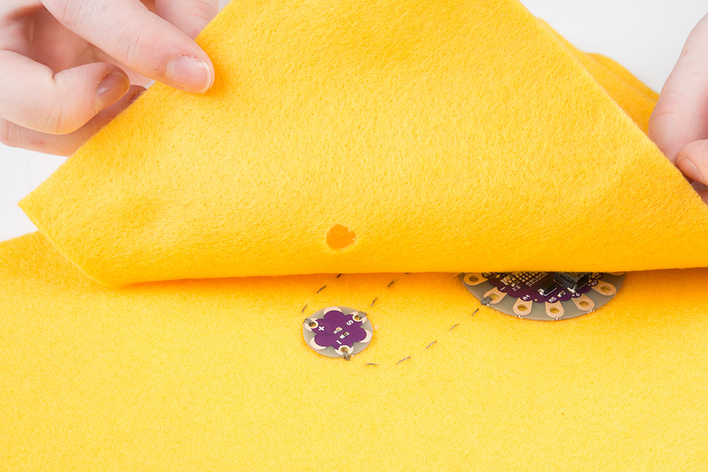
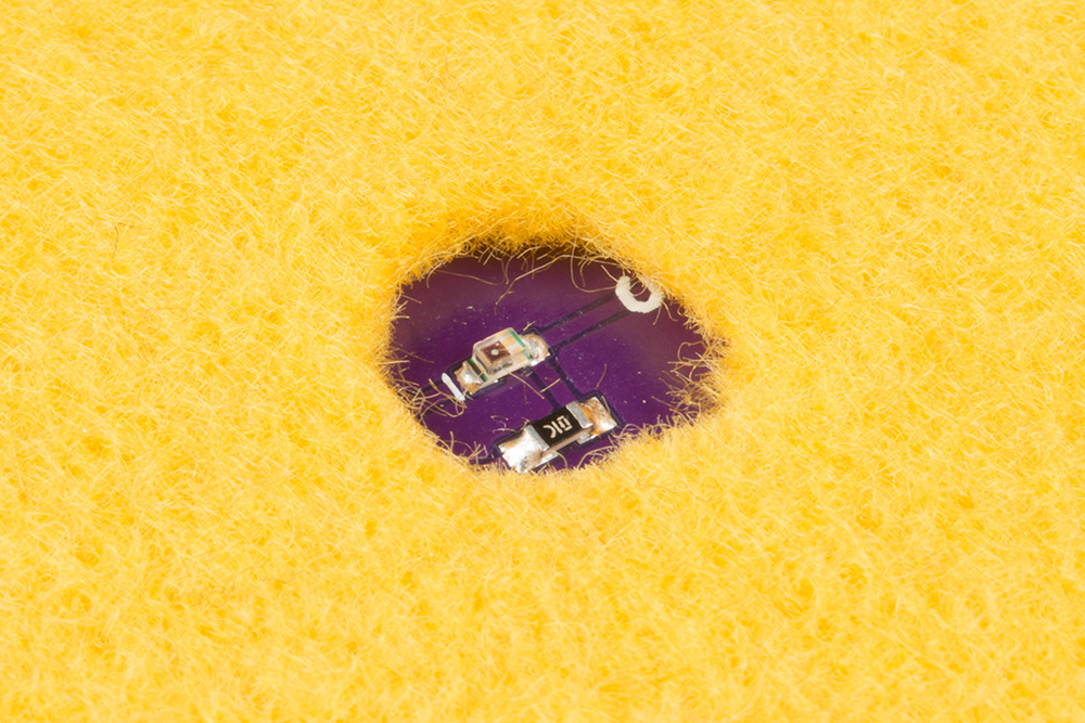
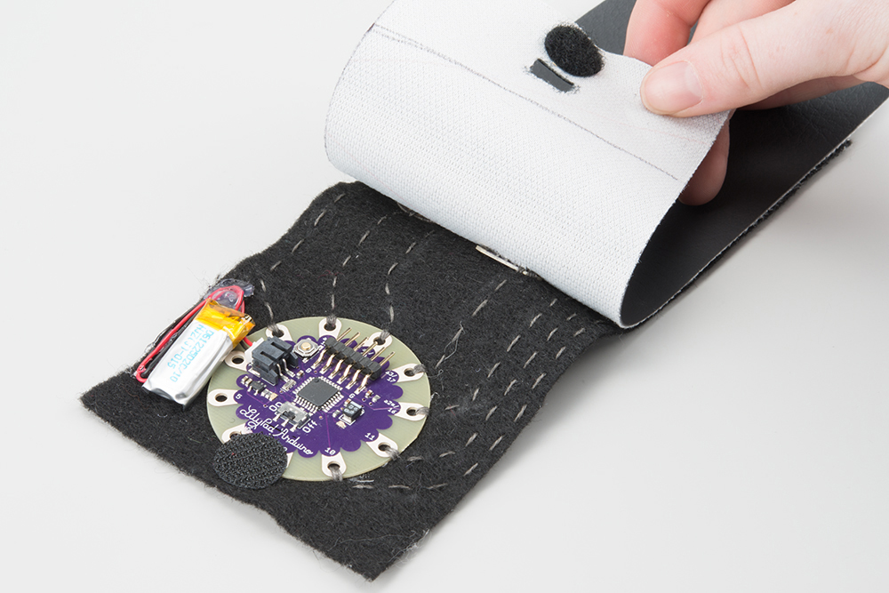
To hide the sensor in your project, you can cover with a material making sure to leave an opening for the sensor to be exposed to light. Cutting a hole above the sensor in fabric is one way to do this.
Project Examples
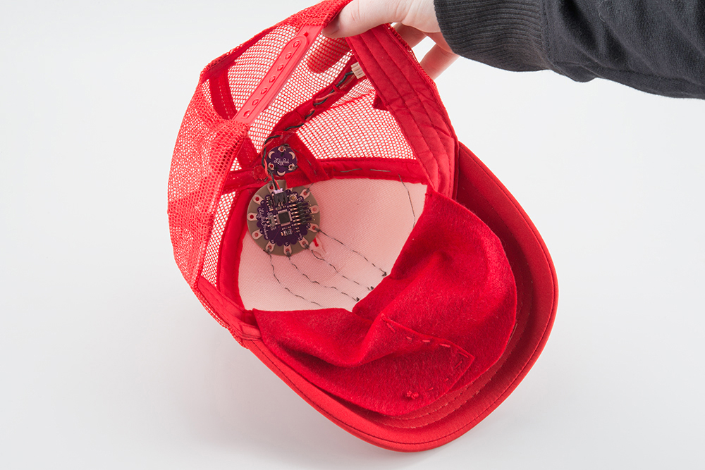
Light Sensitive Hat
Let your geek shine with this hat that blinks when the lights go down.

Musical Bracelet
Combining the sensor with a LilyPad Buzzer can create interesting interactive projects, for example this wearable light-controlled musical instrument or Opto-Theremin. Control tones on the buzzer by covering the LilyPad Light Sensor.
Twinkling Prom Dress
The prom dress project featured in this video uses an initial threshold setting and light sensor to trigger some LilyPad Pixel Boards.
LilyPad Safety Scarf
Create a scarf that lights up when it gets dark with LilyPad and sewable LED ribbon.
LilyPad Safety Scarf
November 21, 2017
Resources and Going Further
Here are some resources for e-textiles and planning a project with the light sensor:
- Schematic (PDF)
- Eagle Files (ZIP)
- Datasheet (PDF)
- Lilypad Landing Page
- Planning a Wearable Electronics Project
- Insulation Techniques for e-Textiles
- SFE Education: LilyPad
- GitHub Repo
- SparkFun Product Showcase: Lilypad Light Sensor
Or, you can check out these other great light-based tutorials: