LilyPad Pixel Board Hookup Guide
 Gella ,
  MikeGrusin
 Introduction
Tired of having to stick with one LED color choice on your LilyPad LED projects? Using addressable LilyPad Pixel Boards allows your project to showcase a variety of colors with less wiring - several of these breakouts can be chained together and controlled by one pin on a LilyPad Arduino. The pixel board is equipped with a WS2812B which is actually an RGB LED with a WS2811 built right into the LED! So set aside some time (and alligator clips) to prototype along with us and then brainstorm how to implement it into a wearable project.
Suggested Reading
This is an intermediate LilyPad project, so we assume you are comfortable with sewing with conductive thread and uploading code to your LilyPad Arduino. Here are some tutorials to review before beginning this project:
- E-Textiles Basics
- Insulation Techniques for E-Textiles
- Short Circuits
- ProtoSnap LilyPad Development Simple Hookup Guide
If you have not worked with WS2812 LEDs (also known as Neopixel LEDs), we recommend visiting this tutorial first:
WS2812 Breakout Hookup Guide
July 24, 2013
Materials and Tools
Let's go over some of the basic supplies you'll need to get started:
- We suggest 3 LilyPad Pixel Boards to start with, but feel free to use more or less in your personal project. See the next section of this tutorial for calculating how many pixels you can power.
- We've also included an optional capacitor which will help to smooth out your power supply and reduce potential flickering of the LEDs in our circuit. See WS2812 tutorial for more details.
Additional Tools:
- Scissors
- Sewing thread (non conductive)
- A project to sew into!
Hooking up LilyPad Pixel Boards
We'll be covering the basics of addressable LEDs for this project, for more detailed information check out our WS2812 Hook Up Guide.
LilyPad Pixel Boards require three types of connections: Power, Ground, and Data. The + and - connect to the respective pins on the LilyPad.
Each board has 2 pairs of Data pins - DI for Data IN and DO for Data OUT. One of the Data IN pins on the pixel will connect to an output pin on the LilyPad (in this tutorial we will be using pin 6).
To connect more than one pixel we'll chain the Data OUT from one pixel to the Data IN of the next pixel. The pixels will be numbered in our code starting with 0 for the closest to the LilyPad pin.
Before we do any sewing, let's create a small pixel chain using alligator clips. We're starting with three pixels to keep the wiring chaos to a minimum. Carefully clip the pixels together as shown in the image below (colors of the clips don't matter, but will make seeing your connections easier as you add more parts):
The pixels don't care which side (left or right) they get power and ground from, we've shown power, ground and data connecting from the left. Notice how in this image the power and data lines cross - this is okay while using insulated alligator clips, but we'll need to carefully plan our conductive thread stitches so we do not cross them in our project.
Using NeoPixel Library and Sample Code
Now it's time to light up our pixels. Adafruit's NeoPixel library is a great way to control these LEDs.
Note: This example assumes you are using the latest version of the Arduino IDE on your desktop. If this is your first time using Arduino, please review our tutorial on installing the Arduino IDE. If you have not previously installed an Arduino library, please check out our installation guide.
For Arduino IDE users, click here to download a copy of the NeoPixel library along with some example code SparkFun has created.
Setup
There are a few lines of code required to set up your sketch to use the library.
language:c
#include <Adafruit_NeoPixel.h>

#define PIN 6
#define LED_COUNT 3

// Create an instance of the Adafruit_NeoPixel class called "leds".
// That'll be what we refer to from here on...
Adafruit_NeoPixel leds = Adafruit_NeoPixel(LED_COUNT, PIN, NEO_GRB + NEO_KHZ800);
The first line of code tells Arduino to add the NeoPixel library to the sketch. Before you upload any code, make sure you adjust the PIN and LED_COUNT definitions near the top of the sketch. These tell our program which pin on the LilyPad the first pixel is connected to, and how many pixels are linked together in the pixel chain. In our example hookup PIN is 6 and LED_COUNT is 3.
The Adafruit_NeoPixel line defines our pixel settings and creates an instance we've named leds.
In order to start controlling the pixels, we'll also need to put the leds.begin() function somewhere near the beginning of the setup() function. See the code below for how all of these things work together.
Setting Individual Pixel Colors
Setting an LED with the Adafruit NeoPixel library is a two step process - first setting the color, then showing that color. To set a pixel's color, we use the leds.setPixelColor(position, color) command. Then, leds.show() will display it on the pixels. Upload the example code below and you should see a different color displayed on each of the three pixels we hooked up earlier.
language:c
/******************************************************************************

LilyPad Pixel Board - Set Colors Example
Angela Sheehan
SparkFun Electronics

Adapted from SparkFun's WS2812 Breakout Hookup Guide code examples

This code demonstrates setting colors on individual LilyPad Pixel Boards using
the NeoPixel library.

******************************************************************************/

#include <Adafruit_NeoPixel.h>

#define PIN 6  //Which pin the pixels are connected to
#define LED_COUNT 3  //Number of pixels used

// Create an instance of the Adafruit_NeoPixel class called "leds".
// That'll be what we refer to from here on...
Adafruit_NeoPixel leds = Adafruit_NeoPixel(LED_COUNT, PIN, NEO_GRB + NEO_KHZ800);

void setup()
{
 leds.begin();  // Start up the LED strip
 leds.show();   // LEDs don't actually update until you call this function
}

void loop()
{
  leds.setPixelColor(0, 255, 0, 0); // Set the first pixel to RED
  leds.setPixelColor(1, 0, 255, 0); // Set the second pixel to GREEN
  leds.setPixelColor(2, 0, 0, 255); // Set the third pixel to BLUE
  leds.show(); //Display the colors
}
Feel free to experiment with creating different colors using different levels of red, green, and blue on each pixel. Using a color picker in graphic design software or a color picker tool can help you find the RGB values for a particular color.
Setting All Pixels
Now let's try setting all the pixels to the same color. Rather than have a line of code for each pixel, we can use a for() loop in our code to cycle through and set each pixel's value.
language:c
/******************************************************************************

LilyPad Pixel Board - Set All Pixels
Angela Sheehan
SparkFun Electronics

Adapted from SparkFun's WS2812 Breakout Hookup Guide code examples

This code demonstrates setting all LilyPad Pixel Boards in the project to one
color using the NeoPixel library.

******************************************************************************/

#include <Adafruit_NeoPixel.h>

#define PIN 6  //Which pin the pixels are connected to
#define LED_COUNT 3  //Number of pixels used

// Create an instance of the Adafruit_NeoPixel class called "leds".
// That'll be what we refer to from here on...
Adafruit_NeoPixel leds = Adafruit_NeoPixel(LED_COUNT, PIN, NEO_GRB + NEO_KHZ800);

void setup()
{
 leds.begin();  // Start up the LED strip.
 leds.show();   // LEDs don't actually update until you call this.
}

void loop()
{
  //Use a for loop to scroll through each pixel
  for(int x=0; x<LED_COUNT; x++)
  {
    //Set the pixel to YELLOW
    leds.setPixelColor(x, 255, 255, 0);
  }
  leds.show(); //Display the color

}
Setting Pixel Brightness
By now, you may have noticed that these pixels can get pretty blindingly bright! Luckily, the library includes a command to set the pixel chain's brightness.
leds.setBrightness(); can be given a value between 0 and 255.
Setting the brightness will not only help save your eyesight, but can also keep the LEDs in the pixels from using a lot of power, which will prolong your project's battery life. Make sure to call leds.show() afterward to display the updated brightness setting.
This sets all of the pixels in the chain's brightness, not each pixel individually. If you want to show varying brightnesses for different pixels, try mixing up a darker version of the color using RGB values.
Here's some example code that uses a potentiometer to adjust the brightness levels in real time:
language:c
/******************************************************************************

LilyPad Pixel Board - Set Brightness
Angela Sheehan
SparkFun Electronics

Adapted from SparkFun's WS2812 Breakout Hookup Guide code examples

This code demonstrates changing the brightness of all LilyPad Pixel Boards in
the project with a potentiometer.

******************************************************************************/

#include <Adafruit_NeoPixel.h>

#define PIN 9  //Which pin the pixels are connected to
#define LED_COUNT 3  //Number of pixels used
int potentiometer = A2;
int brightness;

// Create an instance of the Adafruit_NeoPixel class called "leds".
// That'll be what we refer to from here on...
Adafruit_NeoPixel leds = Adafruit_NeoPixel(LED_COUNT, PIN, NEO_GRB + NEO_KHZ800);

void setup()
{
 // Set the potentiometer as an INPUT:
 pinMode(potentiometer, INPUT);
 // Serial communication so we can view readings from the potentiometer
 Serial.begin(9600);
 leds.begin();  // Start up the LEDs
    //Since the color of the LEDs won't be changing, only the brightness
    // we can use a for loop in setup to set the color once
    for(int x=0; x<LED_COUNT; x++)
    {
      leds.setPixelColor(x, 255, 0, 0); //Set the pixel to RED
    }
 leds.show();   // LEDs don't actually update until you call this.
}

void loop()
{
    // Here we'll use the reading from the potentiometer to set the brightness
    brightness = map(analogRead(potentiometer), 0, 1023, 0, 255);
    leds.setBrightness(brightness); // Set the brightness of the LEDS
    leds.show(); // Display the LEDs
}
Additional Code Examples
For more complicated color patterns, check out the example code included in the library download. Make sure to adjust PIN and LED_COUNT in the sample code to match your project's set up.
Powering Your Pixels
For a general overview of calculating power requirements for your LilyPad project, take a look at our Powering LilyPad LED Projects tutorial. Here, we'll cover special considerations for the LilyPad Pixel Boards.
Unlike most e-textiles parts, LilyPad Pixel Boards use quite a bit of power. If running a project with a 3.7V Lipo battery, each LilyPixel could use as much as 40 milliamps (mA) of current when the color is set to white (all three internal LEDs are fully on). Each additional LilyPixel adds another 40mA to the total, so current draw can add up fast.
LilyPad Pixel Boards start to misbehave when voltage powering them drops below 3 volts. When prototyping with alligator clips, the circuit may have functioned great, but once we sew it into a project with conductive thread resistance can become an issue. The thread on the bobbin averages around 28 Ohms/ft in resistance, which over long distances can the reduce voltage reaching the pixel boards. So what does this mean for project planning?
For successful projects, use as thick a thread as you can, and keep the total power supply stitching as short as possible.
Instead of placing all of the pixels on one power loop, create multiple loops that contain fewer pixels. For example instead of having 10 pixels on one loop, two 5 pixel loops with separate power lines will help decrease thread resistance over distance. One drawback is that this strategy increases the amount of sewing required, and multiple loops can make crossovers difficult.
Preventing Flickering Pixels
Voltage-drop issues can also happen when LilyPad Pixel Boards are commanded to different brightness levels. The change in current draw will create a voltage fluctuation on the power line, causing neighboring pixels to appear to flicker even if they are not being commanded.
We can prevent (or fix) these problems by:
Reducing power line resistance - keep the power lines as short as possible, by using bundled conductive thread or conductive thread alternatives such as conductive fabric with a lower resistance.
Use multiple power loops - use a pixels in short lines instead of all pixels on one long power line.
Switch to wire - some larger projects may benefit from wired pixels instead of conductive thread.
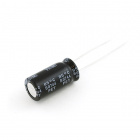
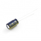
Adding Capacitors
We can also add capacitors to the circuit. Capacitors are an electronic component that acts like power reservoirs. They fill up with voltage when it’s available, and supply it when the voltage drops. This evens out the voltage fluctuations on the power line, greatly reducing flicker.
SparkFun sells 1000 microfarad (uF) capacitors that can be added to your circuit by making loops in the leads and sewing to the loops. Note that there is a positive and negative lead; the negative lead is denoted by a stripe on the body of the capacitor.
Attach capacitors across the power and ground close to the LilyPad Pixel Boards. Because the effects are reduced along the length of the resistive thread, add one capacitor for every five or ten pixels. Sprinkling them throughout the project layout will provide local voltage reservoirs that will help even out the voltage fluctuations.

Project Planning and Examples
Now that we've tested our code and basic circuit hookup, time to make some decisions about how to attach the components to our project. For general tips on planning your project, check out this tutorial:
Planning a Wearable Electronics Project
August 13, 2015
When working with LilyPad Pixel Boards, you'll have to make a lot more decisions regarding power, as well as considering placement of pixels and how they will shine through the project.
As we discovered earlier, the LEDs on the pixels can get pretty bright! Here are some ideas for diffusing the light so that it illuminates in a soft glow instead of a spotlight effect on your project:
- Batting or layers of felt/fabric between pixel and top layer of fabric
- Sequins, beads, or hot glue
- Scrape the mirror backing off of craft gems to create a jewel cover for the pixel
- Light colored fake flower over the pixel
- Ping Pong Balls, bottle caps, or other plastic pieces
Example Projects
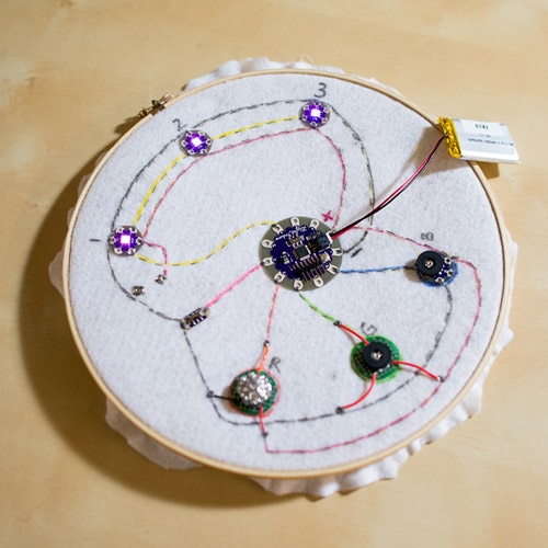
Here is a basic example circuit SparkFun Education uses for teaching LilyPad skills. The snaps are sewn in to demonstrate the difference when a capacitor is in the circuit to eliminate flickering. Both types of potentiometer methods are used, one is covered with a jeweled button to show a method for incorporating into a project.
In this episode of ElectriCute, Dia and Nick show a New Year's Eve dress created with pixel boards and a DeadOn RTC Breakout.
This prom dress project featured in this video uses a LilyPad Light Sensor to trigger some pixel boards in a twinkling pattern.
Resources and Going Further
- Insulation Techniques for e-Textiles - methods for protecting your conductive thread from short circuits in a wearables project.
- Sound and Motion Reactivity for Wearables - Hacker in Residence Matt Pinner shows how to trigger addressable RGBs with sound and motion.
- Re-Programming the LilyTiny/LilyTwinkle - LilyPad Pixels will work with a re-programmed LilyTiny or Twinkle if you want a very small project.