LilyPad ProtoSnap Plus Activity Guide
 MikeGrusin,
  Gella
Gella 
7: Sensing Light
This activity will also use inputs, this time to sense ambient light in the room and use that reading to light up LEDs. The light sensor is an analog sensor which provides a range of values instead of the digital ON/OFF of the buttons and switches example.
LilyPad Boards Used in This Activity
- LilyPad USB Plus
- LilyPad Light Sensor
- Red LilyPad LEDs
- Green LilyPad LEDs
- Blue LilyPad LEDs
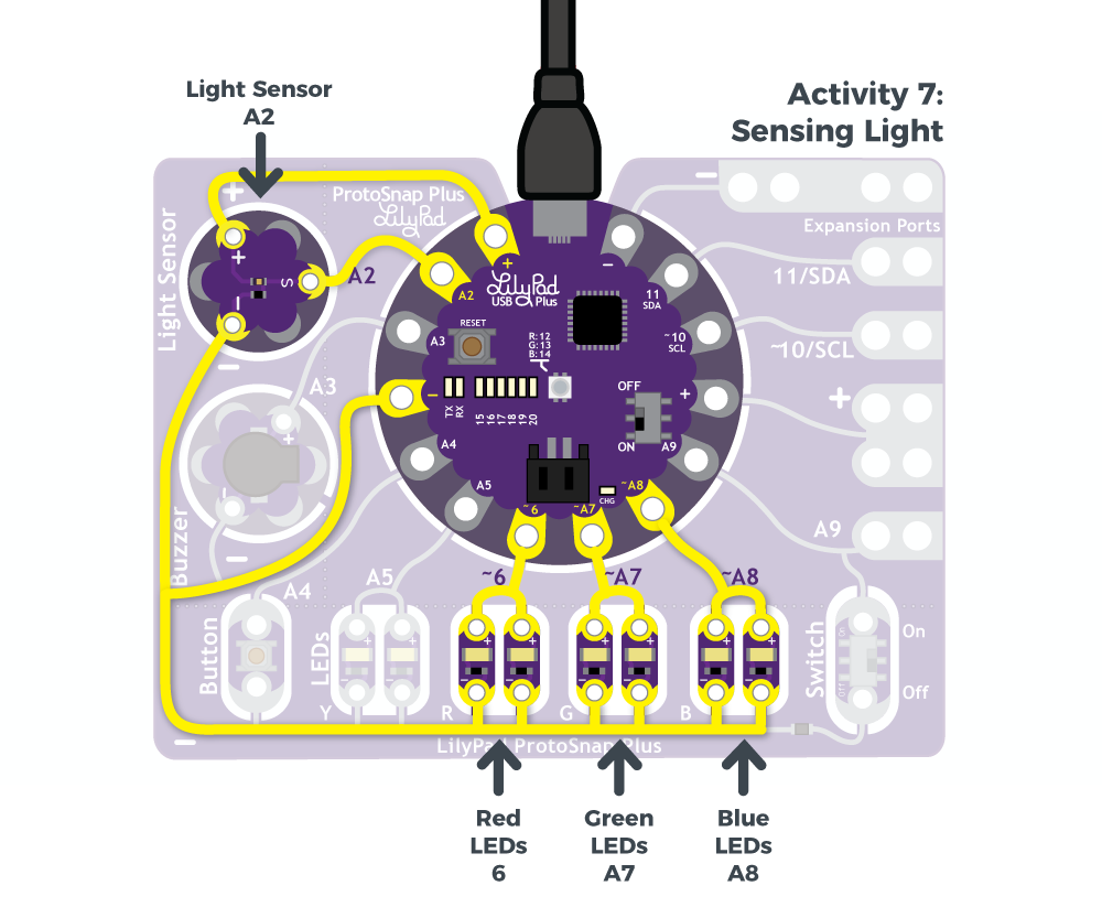
The LilyPad Light Sensor outputs voltage between 0V and 3.3V depending on the level of ambient light shining on it. Unlike the other LilyPad components you've used thus far, the light sensor has three sew tabs - positive, negative, and signal (S). The sensor is hooked up to power and ground tabs on the LilyPad USB Plus and the S tab is hooked up to a sew tab used for analog input.
As more light is applied on the sensor, more current will be able to flow from the board through the signal tab to your LilyPad USB Plus. If the sensor receives no light, no current will flow through it.
New Concepts Introduced in This Activity
Analog Input: Analog to Digital Conversion
In this activity, we’ll explore reading input from a sensor in a new way using analog input. Notice that certain sew tabs on the LilyPad USB Plus include an ‘A’ in front of the number - this indicates the pins on the controller and tabs that are connected have an Analog to Digital Converter (ADC). These pins can “sample” an analog signal being read by the controller and translate it to a digital signal that the controller can interpret.
In the last activity, we used digital inputs that read only two states. The LilyPad Light Sensor is an analog sensor, meaning it can read a wide range of values. For analog inputs, the values range from 0 (0V) to 1023 (3.3V).
Serial Monitor and Serial Commands
When using the button and switch, it was pretty easy to tie the ON/OFF to an LED turning ON/OFF. For sensors reading a range of values, it is more useful to actually see those numbers and make decisions using them. The Serial Monitor and Serial Commands are useful tools for displaying information from variables or other debugging tools for your code.
Example Code
To open the code, go to:
File > Examples > LilyPadProtoSnapPlus > LPP_07_Light
You can also copy and paste the following code into the Arduino IDE. Hit upload, and see what happens!
language:c
/*
LilyPad ProtoSnap Plus Activity 7: Sensing Light
SparkFun Electronics
https://www.sparkfun.com/products/14346

Explore analog input from the light sensor

Follow the tutorial at:
https://learn.sparkfun.com/tutorials/lilypad-protosnap-plus-activity-guide#7-sensing-light

This code is released under the MIT License (http://opensource.org/licenses/MIT)

******************************************************************************/

// Create variables for the pins we'll use:

int sensorPin = A2;

int redLED = 6;
int greenLED = A7;
int blueLED = A8;

void setup()
{
  // Initialize the sensor pin as an input, but without a pullup
  // (Pullups are only used for switch inputs)

  pinMode(sensorPin, INPUT);

  // Initialize the output pins:

  pinMode(redLED, OUTPUT);
  pinMode(greenLED, OUTPUT);
  pinMode(blueLED, OUTPUT);

  // Initialize the serial monitor:

  Serial.begin(9600);
}

void loop()
{
  int sensorValue;

  // Read the sensor value (will be 0 to 1023):

  sensorValue = analogRead(sensorPin);

  // Print out the sensor reading to the serial monitor:

  Serial.print("sensor value: ");
  Serial.println(sensorValue);

  // Since the sensor value is 0 to 1023,
  // and analogWrite needs a value from 0 to 255,
  // we'll divide the sensor value by four to scale it down:

  analogWrite(redLED,sensorValue / 4);
  analogWrite(greenLED,sensorValue / 4);
  analogWrite(blueLED,sensorValue / 4);
}
What You Should See
Hold your hand over the light sensor to change the amount of light it is exposed to and observe the red, green, and blue LilyPad LEDs. As the light sensor reads less light, the LEDs will reflect the light levels with their brightness levels. You can also use a flashlight to shine more light on the sensor and observe how it affects the LEDs.
Understanding Your Program
Program Overview
- Store the light level in the variable
sensorValue. - Print the reading to the Serial Monitor.
- Set the brightness level of the red, green, and blue LEDs to the number stored in the sensorValue variable divided by 4.
- Repeat.
Using the Serial Monitor:
The Serial Monitor is one of the Arduino IDE's many great built-in tools. It can help you understand the values that your program is trying to work with, and it can be a powerful debugging tool when you run into issues where your code is not behaving the way you expected it to. In this activity, you will use the Serial Monitor to print the values from the light sensor to it and observe how they change as the ambient light changes. To see these values, click the Serial Monitor button indicated by the magnifying glass icon in the upper-right corner of the IDE. You can also select Tools > Serial Monitor from the menu.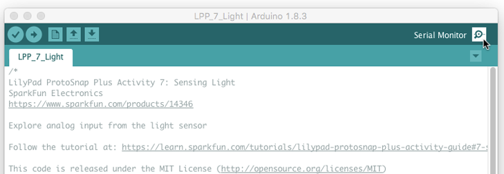
A new window will pop up where you should then see numeric values appear. Cover the light sensor, and you should see the values change as they scroll by.
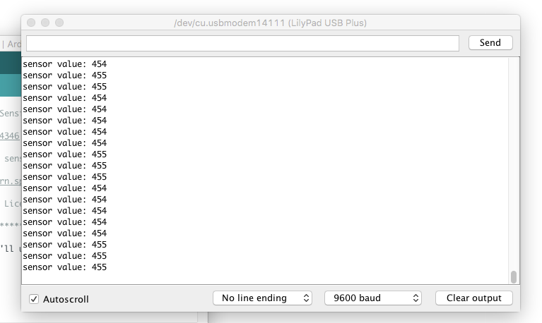
The values on your screen may look different than in this image. The range of readings will depend on the light levels in the room you are working in.

If you are having trouble seeing the values, double check that 9600 baud is selected in the dropdown menu at the bottom right of the window and the auto scroll option is checked.
Code to Note
| Code | Description |
|---|---|
pinMode(sensorPin, INPUT); |
Setting Input:When using analog sensors, you do not need to use anINPUT similar to what you did in the buttons and switches activity. |
Serial.begin(9600); |
Serial Begin:In this program, you will use the Serial Monitor. In order to see anything displayed in the monitor, you must start a serial connection with your LilyPad USB Plus by usingSerial.begin(). This allows the LilyPad USB Plus to send and receive data to your computer. The number 9600 is the communication speed between the devices, called baud rate. The baud rate must match in both your code and the drop down menu in the Serial Monitor. |
sensorValue = analogRead(sensorpin); |
Analog Input:Similar to how you checked for a button or switch state in the last activity, theanalogRead() function reads the value on a pin attached to an analog sensor. In this code the pin is defined as the sensorPin. Unlike digitalRead(), which returns one of two states (HIGH/LOW), this function returns a number between 0 (0 volts) and 1023 (3.3V volts), which is then assigned to the variable sensorValue. |
Serial.print("sensor value: ");Serial.println(sensorValue); |
Serial Print Commands:After opening the communication to the Serial Monitor in setup, you can now send some values to it. The first line prints some descriptive text to the monitor, and the second prints the value stored insensorValue. The ln at the end of print tells the monitor to print a new line at the end of each value; otherwise the values would all run together on one line. Try removing the ln to see what happens.Learn more about the Serial Print commands in the Arduino Reference. |
analogWrite(redLED,sensorValue / 4);analogWrite(greenLED,sensorValue / 4);analogWrite(blueLED,sensorValue / 4);
|
Adjust Brightness:These lines of code use thesensorValue variable to set the brightness of three LEDs. However, remember from the color mixing and fading examples that the analogWrite() can only take a value between 0 and 255, while the sensor will provide values up to four times that number. To get a number the function can use, the program divides the range by 4. |
Coding Challenges
Can you change the code so that the built-in RGB LED displays a brighter or dimmer white when the light levels change?
Can you change the code so that two colors mix on the RGB LED when the light levels change?
Can you create a blink pattern where the speed of the blink is determined by the light sensor readings?