LilyPad Vibe Board Hookup Guide
 bboyho
 Gella
Gella Attaching to a LilyPad Arduino
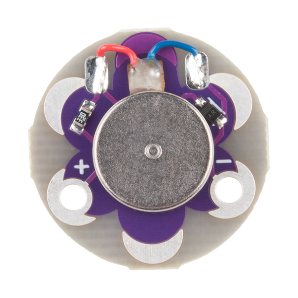
The LilyPad Vibe Board has two sew tabs: Power (+) and Ground (--). Next to each tab is a white label for reference. For power, you can connect an input voltage anywhere between 3.3V and 5V. The motor can vibrate faster as you provide more voltage. We recommend connecting the (+) tab to a MOSFET to drive the motor when using it with an Arduino due to the amount of current each I/O pin can source . To adjust the intensity, we recommend using a PWM capable sew tab on a LilyPad Arduino.
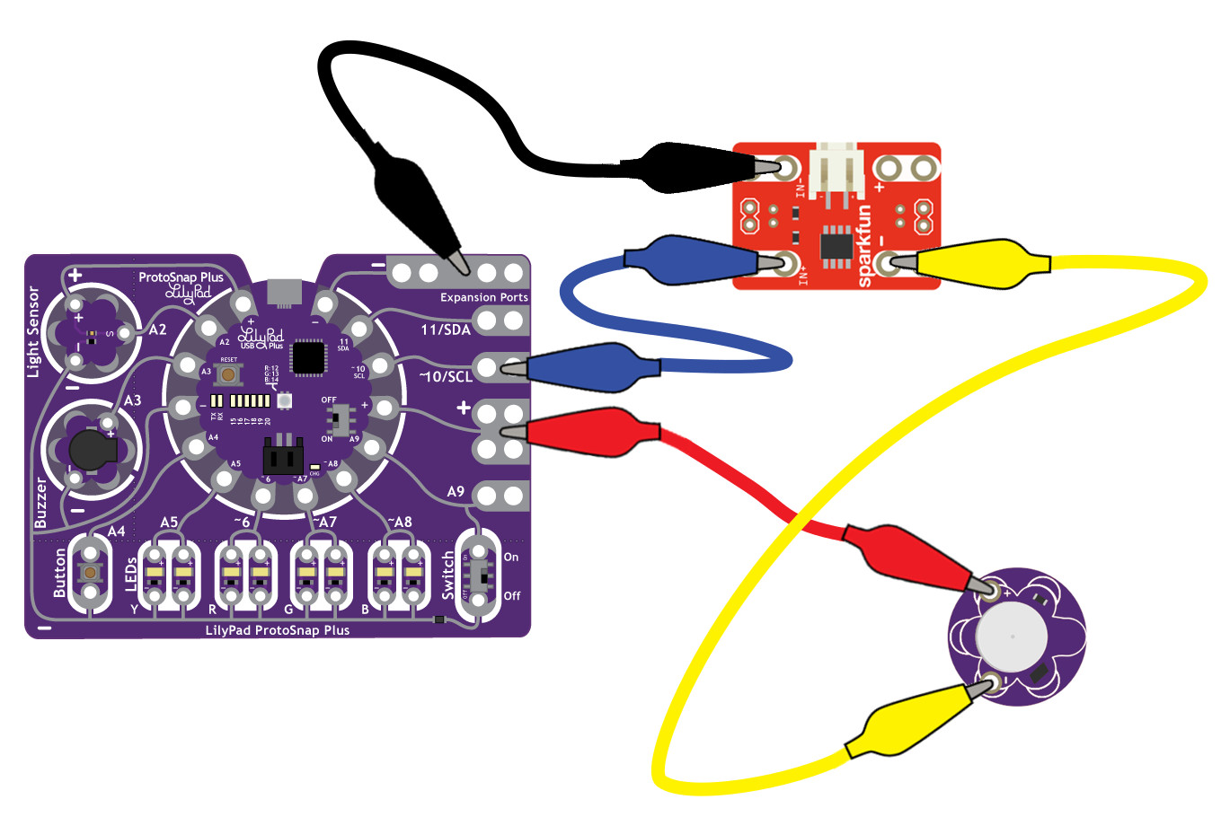
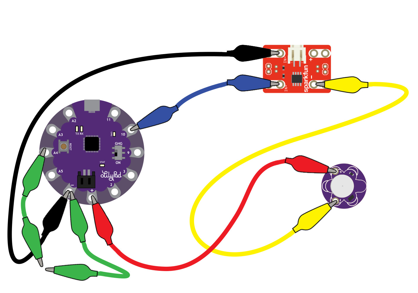
To follow along with the code examples in this tutorial, connect the vibe board and transistor to a LilyPad Arduino as shown in the images below. Use alligator clips to temporarily connect the circuit. Connect the LilyPad's "+" sew tab to the "+" sew tab of the vibe board. Make another connection between the "--" sew tab and the MOSFET power controller's "--" sew tab. Keep in mind that the "--" label on the MOSFET power controller does not represent ground (GND or "--"). Ground is represented as "IN--". The "IN--" should be connected to a LilyPad Arduino's "--" sew tab.
To control the vibe board, connect a PWM pin (pin 10 in the following cases) to the "IN+". When testing the example for button feedback, simply connect A4 to the LilyPad Arduino's "--" ground sew tab. After you are finished prototyping, replace the alligator clips with conductive thread traces for permanent connection in your project.