LIS3DH Hookup Guide
 MTaylor
Example: I2C, analog, and interrupts
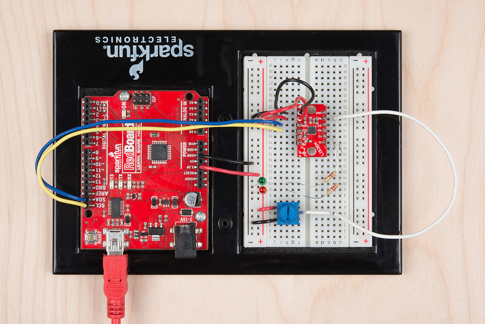
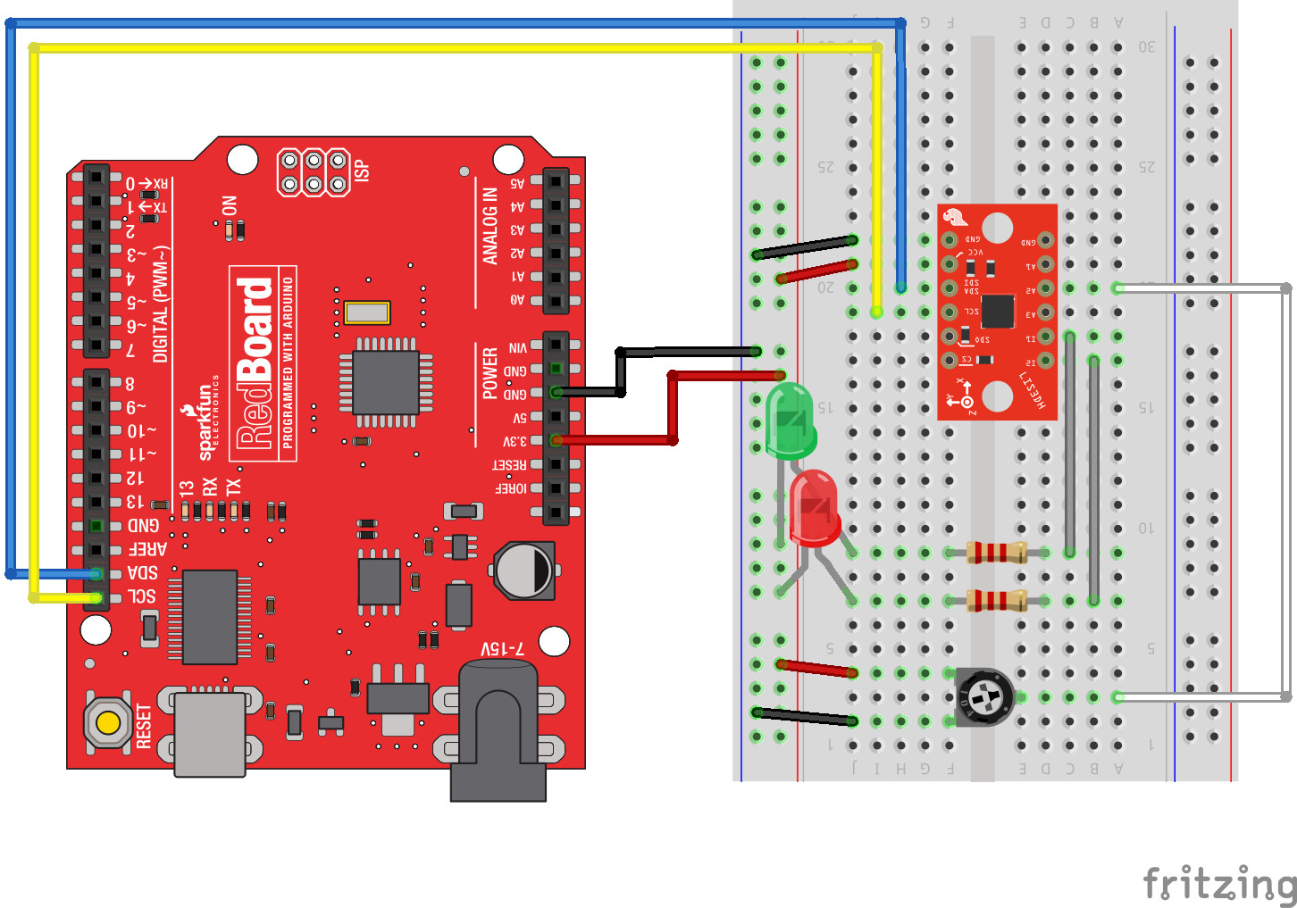
The first circuit allows a RedBoard to talk to the LIS3DH over I2C and provides connections on the interrupt and ADC pins.
The interrupts are useful to indicate conditions like extreme Gs or freefall, and to tell the RedBoard that the FIFO is full and needs to be serviced. The analog input pins are useful to measure various voltages similar to the RedBoard's analog inputs, but have a more constrained voltage range (about 0.9V to 1.8V). If you don't need either of these, just connect power, ground, and communication pins, and ignore the interrupt and ADC examples.
Use these two pictures as a guide for building the circuit.
Basic Accelerometer Data Collection:
Start with just the basic accelerometer sketch, also called "MinimalistExample" from the library. This will periodically samples the sensor and displays data as number of Gs detected. Remember, the vertical axis will read 1G while sitting at rest.
language:c
#include "SparkFunLIS3DH.h"
#include "Wire.h"
#include "SPI.h"

LIS3DH myIMU; //Default constructor is I2C, addr 0x19.

void setup() {
  // put your setup code here, to run once:
  Serial.begin(9600);
  delay(1000); //relax...
  Serial.println("Processor came out of reset.\n");

  //Call .begin() to configure the IMU
  myIMU.begin();

}


void loop()
{
  //Get all parameters
  Serial.print("\nAccelerometer:\n");
  Serial.print(" X = ");
  Serial.println(myIMU.readFloatAccelX(), 4);
  Serial.print(" Y = ");
  Serial.println(myIMU.readFloatAccelY(), 4);
  Serial.print(" Z = ");
  Serial.println(myIMU.readFloatAccelZ(), 4);

  delay(1000);
}
Example output:
Processor came out of reset.


Accelerometer:
 X = -0.1481
 Y = -0.1361
 Z = 0.9768

Accelerometer:
 X = -0.1481
 Y = -0.1361
 Z = 0.9768

Accelerometer:
 X = -0.1481
 Y = -0.1361
 Z = 0.9768

Accelerometer:
 X = -0.1481
 Y = -0.1361
 Z = 0.9768
When run, the sketch will display data in Gs to the serial terminal. Every second, the data is collected and printed.
Using the ADC
To try out the analog inputs, load the example called "ADCUsage", or copy paste from the following section. This example also shows some of the additional settings that can be applied within the begin() function.
language:c
#include "SparkFunLIS3DH.h"
#include "Wire.h"
#include "SPI.h"

LIS3DH myIMU; //Default constructor is I2C, addr 0x19.

void setup() {
  // put your setup code here, to run once:
  Serial.begin(9600);
  delay(1000); //relax...
  Serial.println("Processor came out of reset.\n");

  myIMU.settings.adcEnabled = 1;
  //Note:  By also setting tempEnabled = 1, temperature data is available
  //on ADC3.  Temperature *differences* can be read at a rate of
  //1 degree C per unit of ADC3
  myIMU.settings.tempEnabled = 0;
  myIMU.settings.accelSampleRate = 50;  //Hz.  Can be: 0,1,10,25,50,100,200,400,1600,5000 Hz
  myIMU.settings.accelRange = 2;      //Max G force readable.  Can be: 2, 4, 8, 16
  myIMU.settings.xAccelEnabled = 0;
  myIMU.settings.yAccelEnabled = 0;
  myIMU.settings.zAccelEnabled = 0;

  //Call .begin() to configure the IMU
  myIMU.begin();

}

void loop()
{
  //Get all parameters
  Serial.print("\nADC:\n");
  Serial.print(" 1 = ");
  Serial.println(myIMU.read10bitADC1());
  Serial.print(" 2 = ");
  Serial.println(myIMU.read10bitADC2());
  Serial.print(" 3 = ");
  Serial.println(myIMU.read10bitADC3());

  delay(300);
}
Example output:
Processor came out of reset.


ADC:
 1 = 1020
 2 = 522
 3 = 506

ADC:
 1 = 1020
 2 = 544
 3 = 516

ADC:
 1 = 1020
 2 = 540
 3 = 517
The sketch prints the three ADC values every 300ms. Move the knob to see how the values change and how the effective voltage range is somewhat in the middle of the full range. Move the wire from on ADC pin to another to see that the controlled value changes.
Using the Interrupt Pins
Interrupt behavior is highly configurable and is thus omitted as basic library functions. Instead, LIS3DH registers are directly written in accordance with the datasheet.
An example is provided that has the relevant registers configured with comments in a template function that can be copied into a project and modified. Run the example named IntUsage, which will throw an interrupt on one pin when an exceeded acceleration is detected and a pulse on the other when a tap is detected.