LIS3DH Hookup Guide
 MTaylor
Example: SPI and FIFO usage
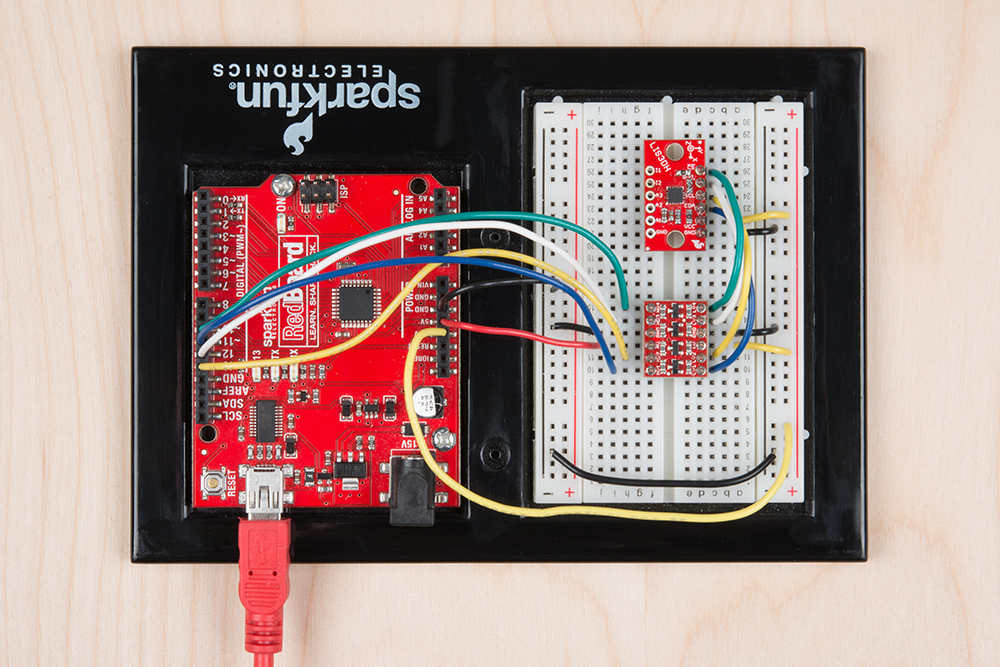
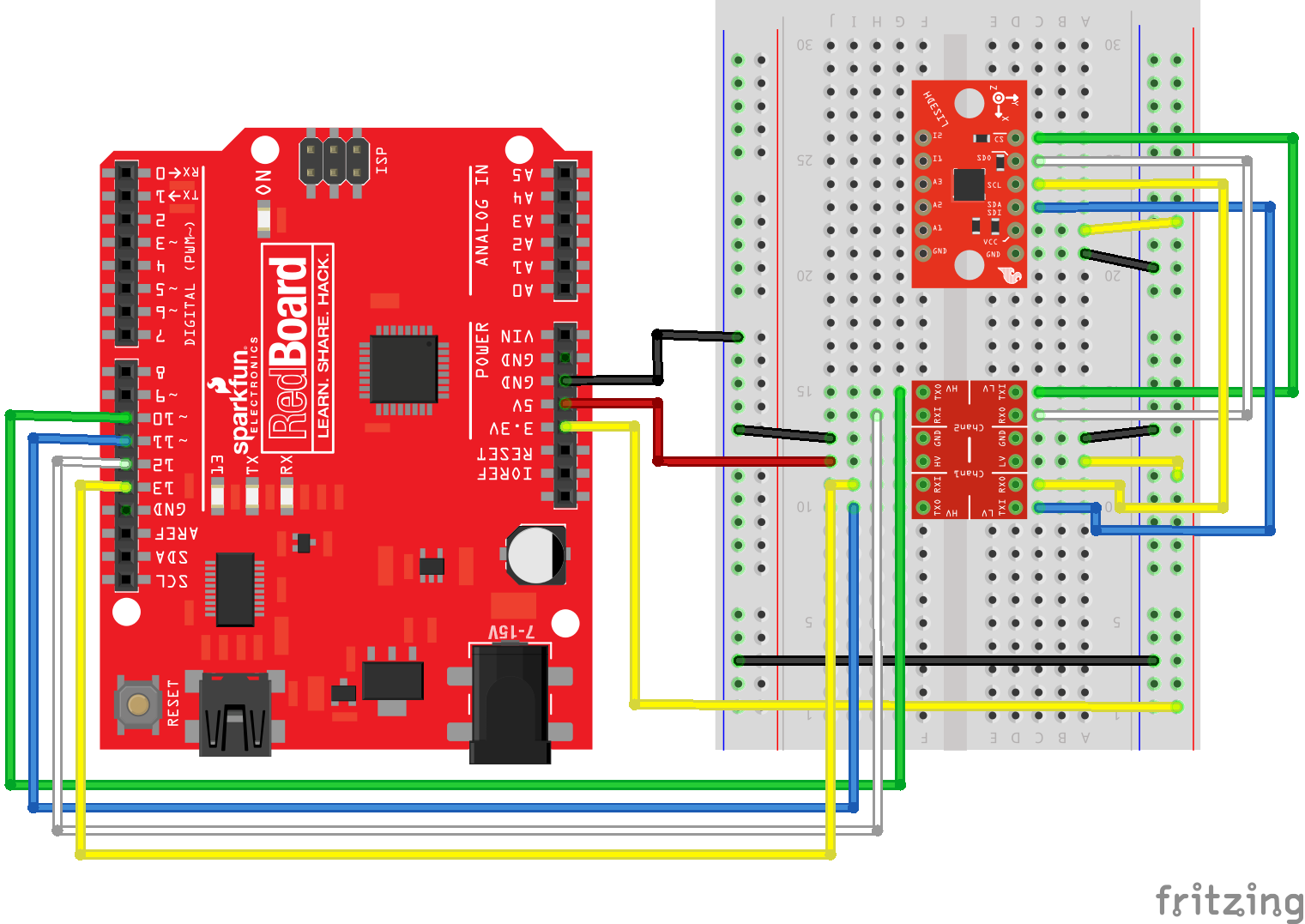
The second method in which to communicate with the LIS3DH is with the SPI interface. The SPI interface operates at 3.3v, so use a logic level converter or a MCU that operates at 3.3V. Use the following pictures to help build the circuit.
Basic Accelerometer Data Collection:
SPI is not the default configuration, so you'll have to pass extra information to the library by constructing with parameters. Modify "MinimalistExample" by changing LIS3DH myIMU; to LIS3DH myIMU(SPI_MODE, 10); for SPI mode with the !CS pin connected to pin 10.
The modified "MinimalistExample" is listed here:
language:c
#include "SparkFunLIS3DH.h"
#include "Wire.h"
#include "SPI.h"

LIS3DH myIMU(SPI_MODE, 10); // constructed with parameters for SPI and cs pin number

void setup() {
  // put your setup code here, to run once:
  Serial.begin(9600);
  delay(1000); //relax...
  Serial.println("Processor came out of reset.\n");

  //Call .begin() to configure the IMU
  myIMU.begin();

}


void loop()
{
  //Get all parameters
  Serial.print("\nAccelerometer:\n");
  Serial.print(" X = ");
  Serial.println(myIMU.readFloatAccelX(), 4);
  Serial.print(" Y = ");
  Serial.println(myIMU.readFloatAccelY(), 4);
  Serial.print(" Z = ");
  Serial.println(myIMU.readFloatAccelZ(), 4);

  delay(1000);
}
Example output:
Processor came out of reset.


Accelerometer:
 X = -0.1481
 Y = -0.1361
 Z = 0.9768

Accelerometer:
 X = -0.1481
 Y = -0.1361
 Z = 0.9768

Accelerometer:
 X = -0.1481
 Y = -0.1361
 Z = 0.9768

Accelerometer:
 X = -0.1481
 Y = -0.1361
 Z = 0.9768
When run, the sketch will display data in Gs to the serial terminal. Every second, the data is collected and printed.
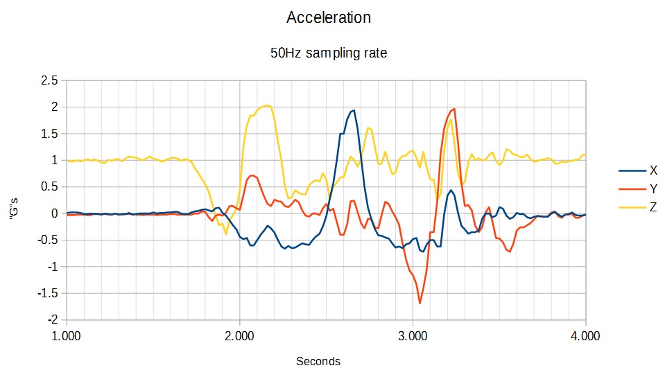
FIFO usage:
The SPI bus can operate faster than I2C, so for high speed data collections where periodic sampling is required, SPI is advisable.
language:c
#include "SparkFunLIS3DH.h"
#include "Wire.h"
#include "SPI.h"

LIS3DH myIMU(SPI_MODE, 10); //Constructing with SPI interface information
//LIS3DH myIMU(I2C_MODE, 0x19); //Alternate constructor for I2C

uint32_t sampleNumber = 0; //Used to make CSV output row numbers

void setup() {
  // put your setup code here, to run once:
  Serial.begin(9600);
  delay(1000); //relax...
  Serial.println("Processor came out of reset.\n");

  myIMU.settings.adcEnabled = 0;
  //Note:  By also setting tempEnabled = 1, temperature data is available
  //instead of ADC3 in.  Temperature *differences* can be read at a rate of
  //1 degree C per unit of ADC3 data.
  myIMU.settings.tempEnabled = 0;
  myIMU.settings.accelSampleRate = 10;  //Hz.  Can be: 0,1,10,25,50,100,200,400,1600,5000 Hz
  myIMU.settings.accelRange = 2;      //Max G force readable.  Can be: 2, 4, 8, 16
  myIMU.settings.xAccelEnabled = 1;
  myIMU.settings.yAccelEnabled = 1;
  myIMU.settings.zAccelEnabled = 1;

  //FIFO control settings
  myIMU.settings.fifoEnabled = 1;
  myIMU.settings.fifoThreshold = 20;  //Can be 0 to 31
  myIMU.settings.fifoMode = 1;  //FIFO mode.
  //fifoMode can be:
  //  0 (Bypass mode, FIFO off)
  //  1 (FIFO mode)
  //  3 (FIFO until full)
  //  4 (FIFO when trigger)

  //Call .begin() to configure the IMU (except for the fifo)
  myIMU.begin();

  Serial.print("Configuring FIFO with no error checking...");
  myIMU.fifoBegin(); //Configure fifo
  Serial.print("Done!\n");

  Serial.print("Clearing out the FIFO...");
  myIMU.fifoClear();
  Serial.print("Done!\n");
  myIMU.fifoStartRec(); //cause fifo to start taking data (re-applies mode bits)

}

void loop()
{
  //float temp;  //This is to hold read data
  //uint16_t tempUnsigned;
  //
  while(( myIMU.fifoGetStatus() & 0x80 ) == 0) {};  //Wait for watermark

  //Now loop until FIFO is empty.
  //If having problems with the fifo not restarting after reading data, use the watermark
  //bits (b5 to b0) instead.
  //while(( myIMU.fifoGetStatus() & 0x1F ) > 2) //This checks that there is only a couple entries left
  while(( myIMU.fifoGetStatus() & 0x20 ) == 0) //This checks for the 'empty' flag
  {
      Serial.print(sampleNumber);
      Serial.print(",");
      Serial.print(myIMU.readFloatAccelX());
      Serial.print(",");
      Serial.print(myIMU.readFloatAccelY());
      Serial.print(",");
      Serial.print(myIMU.readFloatAccelZ());
      Serial.println();
      sampleNumber++;
  }

}
Example output:
Processor came out of reset.

Configuring FIFO with no error checking...Done!
Clearing out the FIFO...Done!
0,-0.15,-0.14,1.04
1,-0.17,-0.12,1.02
2,-0.21,-0.10,0.95
3,-0.21,-0.10,1.01
4,-0.22,-0.12,1.07
5,-0.17,-0.12,0.99
6,-0.12,-0.15,0.96
7,-0.18,-0.12,0.94
8,-0.19,-0.10,0.98
9,-0.20,-0.14,1.04
10,-0.19,-0.12,0.99
11,-0.20,-0.10,0.95
12,-0.21,-0.12,1.06
13,-0.14,-0.12,0.98
14,-0.10,-0.11,0.95
15,-0.12,-0.10,0.94
16,-0.14,-0.09,0.90
...
Notice that the output produces batches of data periodically. Even though the data waits to be collected, it is still sampled periodically. The data is collected when the FIFO is past the watermark configured in the line myIMU.settings.fifoThreshold = 20;.