LogicBlocks & Digital Logic Introduction
 jimblom
LogicBlocks Fundamentals
There are six separate LogicBlocks, which can be divided into three categores: logic gates, input blocks and utility blocks.
Logic Gate Blocks
There are three different logic gate LogicBlocks: AND, OR, and NOT - the fundamental logic gates. They're shaped (as much as possible) like their circuit diagram equivalents, and also labeled with their gate name.
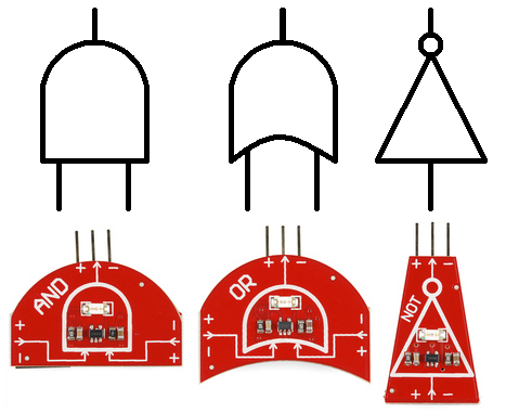
Each gate has one output, a male header (the pointy one). The female headers represent the inputs; the AND and OR gates have two inputs, while the NOT gate has just one.
The logic gate LogicBlocks each have an LED, which represents their output status. An illuminated LED represents a logic gate producing a 1, while an unlit LED means the gate is producing a 0.
Input Blocks
The input blocks are what you'll use to supply LogicBlocks with digital inputs. They have a switch to set the output of the Input block to either 0 or 1. The LED on the Input block displays what value the block is sending out.
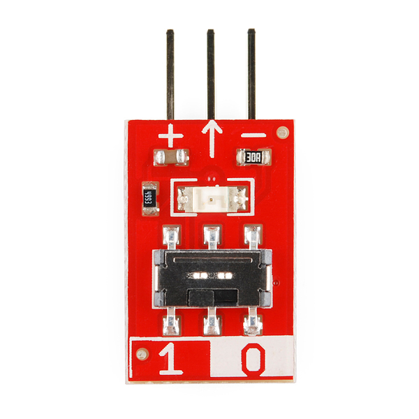
The input blocks have a single, male, output header. This should be plugged into the female inputs of the gate LogicBlocks.
Utility Blocks (and Cables)
Key among the utility boards is the Power block. Each Logic gate requires power to operate, and this board is there to supply it. The Power block has a single, female, input header, and should be plugged into the output of the last logic gate. You'll only need ONE power block to supply power to an entire digital logic circuit.
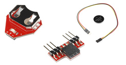
There's also a Splitter LogicBlock, which simply divides one input into two outputs. It doesn't perform any operation on the signal, just passes it through. This'll come in handy when you create more complicated digital logic circuits which require one input to run into two or more logic gates.
Also lumped into this category is the feedback cable. This cable will usually be used in conjunction with the splitter block, for more advanced LogicBlock circuits.
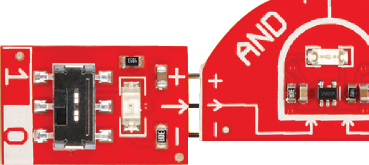
The Rules
There's really only one rule when it comes to playing with LogicBlocks: When connecting an output of one block to the input of another, make sure each of the three pins match up. Each of the inputs and outputs consist of three pins: Power (“+”), Ground (“−”), and Signal (“->”).
You'll also need to make sure there's always one (and only one) Power Block connected to your LogicBlock circuit.
All inputs of a logic block (or cable) should have the output of another block (or cable) attached to them. If an input is left floating (not connected), the gate won't know if the input is a 1 or a 0, and, as a result, the output will be unreliable.
Response Times
Logic gates form their output decisions faster than any human could ever detect (we're talking nanoseconds). So to make the process more visible, we've slowed the LogicBlocks down so you can see the process they go through. If you've got a long line of logic blocks, this delay will allow you to more visually see how the outcome of one block affects the input of another.
The delay is on the order of half a second. Just long enough to see what's going on.