LP55231 Breakout Board Hookup Guide
 Byron J.
Execution Engines
The most interesting features in the LP55231 are the three execution engines. These are three simple, independent, computers that can be programmed to perform LED-related tasks. Before we can look at code written to run on them, we need a little more complete concept of what's inside and how it works.
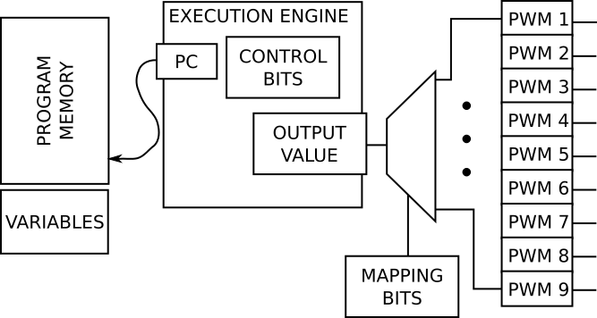
Each engine has the following structure:
- Program memory -- RAM locations, accessed via I2C, that store the program. The LP55231 has memory for 96 locations that store 16-bit instructions, shared between all three engines.
- Program Counter or PC -- a 7-bit value that indicates which RAM location stores the current instruction.
- Variables -- there are 4 variables that can be shared among the engines.
- Control bits -- a few bits that tell the engine how to execute the program. They instruct the engine to run, halt or step by one instruction.
- Output value -- each engine calculates a single output value.
- Mapping bits -- the engine output can control one or more LEDs, as assigned by the mapping bits.
Execution Model
Each engine is a simple Fetch-Execute Machine. A Fetch-Execute Machine is the basis for a computer. When we think of a computer, we usually think of a general-purpose machine that can be programmed to accomplish many different tasks, such as writing documents or performing mathematical work. In contrast, this one is tailored to LED-specific tasks.
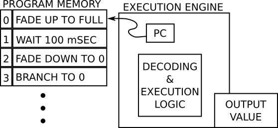
It works like this:
- To initialize the machine, instructions are loaded into the program memory.
- The program counter is set to the first instruction in the program.
- The machine starts running.
- The engine uses the PC to fetch an instruction from the program memory.
- It decodes the instruction, and executes it by performing the actions it describes.
For example, when the program in the diagram above starts, the PC is pointing at location 0, so the engine fetches the instruction FADE UP TO FULL. The engine would increment the output value until it reaches maximum, then increment the PC and fetch the next instruction.
Instruction Set
The 96 words of program memory mentioned above store a program, which is a series of encoded commands, or Instructions. Within the 16-bit words, some bits describe the action to be taken, while others modify that action, specifying things like brightness levels, channel mapping and ramp times.
The LP55231 instruction set is broken into four categories.
Driver instructions
This group of instructions effects the LED output of the engine. The output can be set directly, instructed to ramp from one value to another, or simply pause for a specified time.
Mapping instructions
Each engine calculates a single output value. The engine output can be routed to a single LED with the MUX_SEL instruction.
The mapping instructions can also send that value to multiple outputs, using an indirection table. The table contains one or more bitmaps that describe the outputs controlled by the engine -- the LSB maps to output 1, the next bit to output 2, and so on, using 9 bits. The program uses instructions to select the outputs by referencing the table entries.
A table can be composed of multiple entries, and output selections sequenced by selecting new rows in the table. We'll show how to use this in the following example.
Branch instructions
Ordinarily, as the program executes, the PC increments to select the next instruction. The BRANCH instructions change this behavior.
Branches cause the program counter to be loaded with a new value, to create loops and conditional execution (like for or if statements).
The Interrupt instruction allows the LP55231 to notify the microcontroller that it has reached a specified line in the program. The Trigger instruction makes the engine wait until certain conditions (such as a logic level on the Trig input) are present.
There are also RST and END instructions. Reset causes the program to start over form the beginning, while End causes the engine to halt.
Arithmetic instructions
Finally, the LP55231 can perform addition and subtraction on values stored in the variables.
More Information
A detailed description of every instruction is in section 7.6 of the LP55231 datasheet.
Now that we have a conceptual model of the execution engines, let's move on to an example that applies them.