LS20031 5Hz (66 Channel) GPS Receiver Hookup Guide
 bboyho
Introduction
Congratulations on your purchase of the Locosys LS20031 5Hz 66 Channel GPS module! This low power GPS receiver can tell you where you are five times a second! Where are you now? How about now? I bet you don't know and that's why you need to get your LS20031 working. In this tutorial, we will add headers and read the output using an Arduino. So let's get started...
Required Materials
To follow along with this tutorial, you will need the following materials. You may not need everything though depending on what you have. Add it to your cart, read through the guide, and adjust the cart as necessary.


Tools
You will need a soldering iron, solder, and general soldering accessories.


Suggested Reading
If you aren’t familiar with the following concepts, we recommend checking out these tutorials before continuing.
How to Solder: Through-Hole Soldering
Serial Communication
GPS Basics
Installing an Arduino Library
How to Install FTDI Drivers
Bi-Directional Logic Level Converter Hookup Guide
Hardware Overview
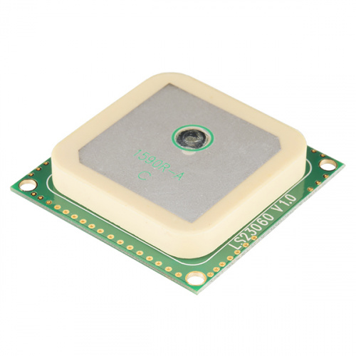
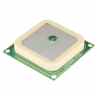
The LS20031 is a high performance, reliable, and inexpensive GPS module. It is a great choice, since it has a 5Hz update rate, a backup power source for quick locks (time to first fix), and a small form factor. The only downside is that it doesn't come with a connector. There is some minor assembly required, but it is very simple.
GPS Module
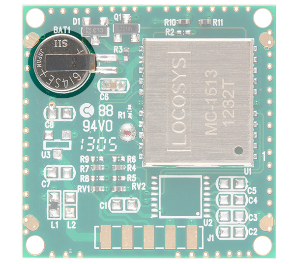
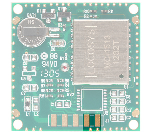
The LS20031 uses the MediaTek MT3339, which can acquire up to 66 satellites at a time. The GPS module has a fast time to first fix (TTFF) and high sensitivity for applications that require navigation and tracking in dense foliage and urban canyons environments.
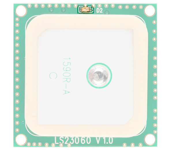
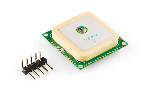
Built-In GPS Antenna
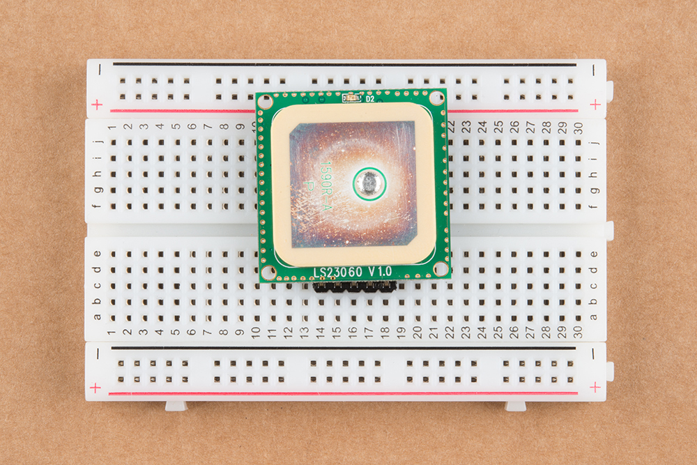
The ceramic patch antenna is the large tan and white object soldered onto the green PCB. Make sure to always point the antenna towards the sky!
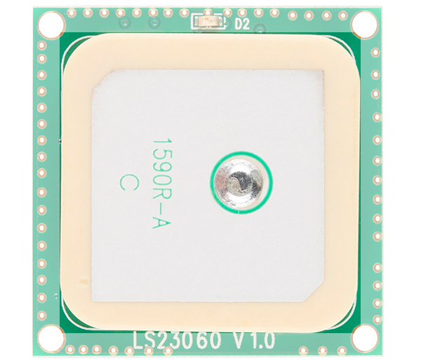
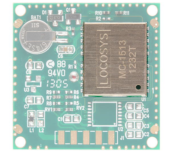
Status LED
There is a red status LED that blinks when there is a fix. A fix means there are enough satellites in view to accurately calculate your position. Once there is a lock in continuous power mode, it will flash once per second when the position is fixed. Otherwise, this LED will remain off.
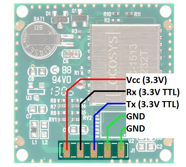
Pinout
The input voltage is 3.3V. The Rx and Tx pins are 3.3V TTL tolerant. This means you will need a logic level conversion if you are using this with a 5V Arduino. The pinout is shown below for the bottom and top views. When using right angle headers and connecting the GPS receiver to a breadboard, the pins are mirrored. Make sure to connect to the correct pins when viewing from either side!
 |
 |
| Pinout of the Back View | Pinout of the Top View |
Commands can be sent to the module to configure settings. There is a handy program called Mini GPS that will help you configure your module. More information about configuration can be found on a blog post by DIY Drones: Using the 5Hz Locosys GPS with Arduino/ArduPilot. Configurable 10Hz update rate means you can get valid position, time, etc. data 10 times a second. Default setting is 1Hz.
Battery Backup
The LS20031 has a built-in battery to reserve system data. This allows for rapid satellite acquisition for cold starts.
Hardware Assembly
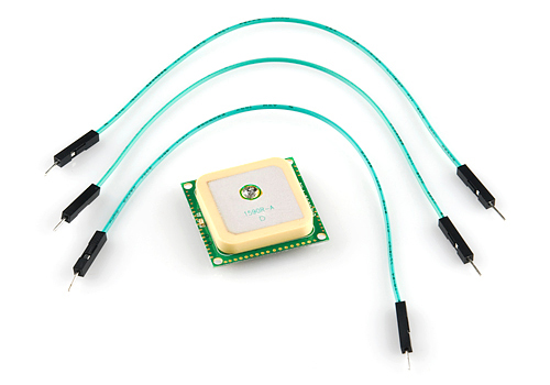
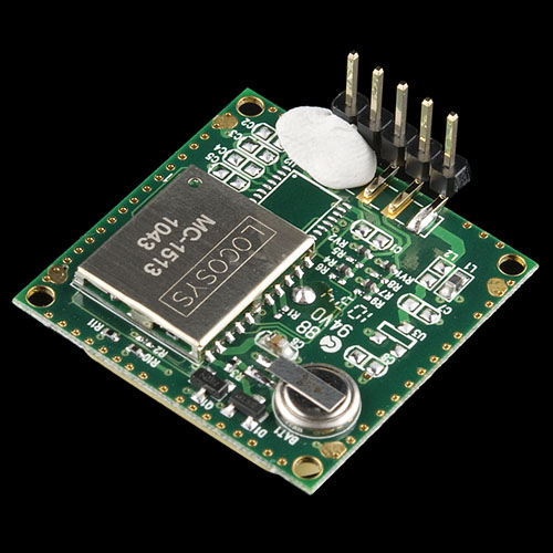
The LS20031 module does not have a connector attached. In order get data from the unit, we need to attach a connector or some connecting wires. Whatever method of connection you use, remember it is important to keep the square ceramic antenna so it is pointed toward the sky. Break off 1x5 row of right angle headers to solder to the GPS receiver.
The most difficult part of the assembly process is probably keeping the right-angle header connector aligned while soldering the pins to the GPS receiver. We'll use sticky tack to hold the pins down against the board. Temporarily fasten one of the outside pins of the connector in place ensuring that all the connector pins overlap the appropriate gold-colored pads on the GPS module circuit board.
Once you're satisfied with the position of the connector, solder the pin at the opposite end of the connector. You can use more solder than you might normally as it will need to provide structural support in addition to electrical contact. As usual, try not to hold the soldering iron in contact for more than a few seconds. Also, make sure you don't accidentally de-solder any of the other components on the board or flick solder onto the board. When you've soldered the first pin it should look similar to this.
Next remove the temporary adhesive and ensure the pins are still aligned correctly on the pads—if they're not, apply heat to the already soldered connector and gently move the connector into alignment. Then solder the other outside pin into place.
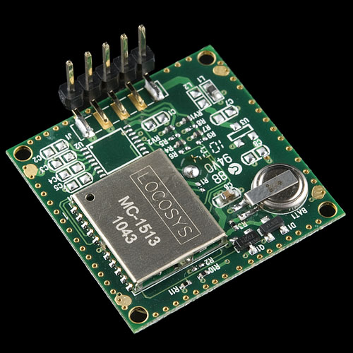
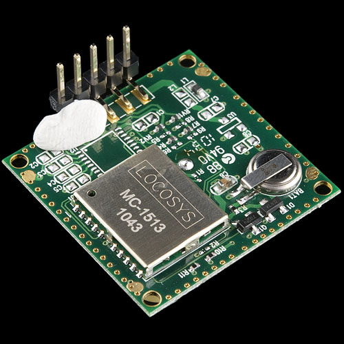
Finally, solder the remaining three pins to their pads. With the two outside pins in place the remaining pins should stay in alignment with the pads. When you've finished your module should look something like the image below.
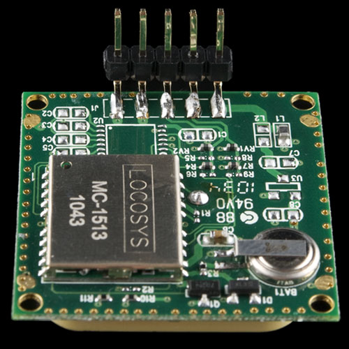
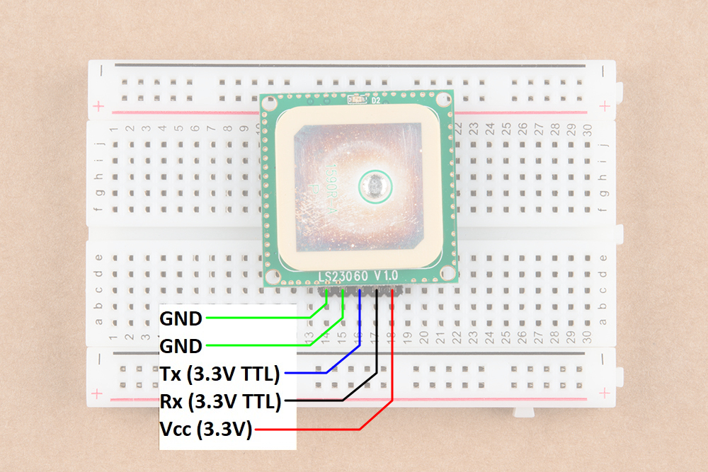
Now that your GPS module has a right-angle connector you can plug it directly into a breadboard. We recommend inserting the headers close to the center of the breadboard for a secure connection and stability.
Hardware Hookup
The simplest method of reading the serial UART output from a GPS receiver is to use a USB-to-serial converter (i.e. an FTDI). However, you can also use a microcontroller to read the output for embedded projects. For the scope of the tutorial, we will focus on two methods of connecting to the GPS receiver. Let's get started.
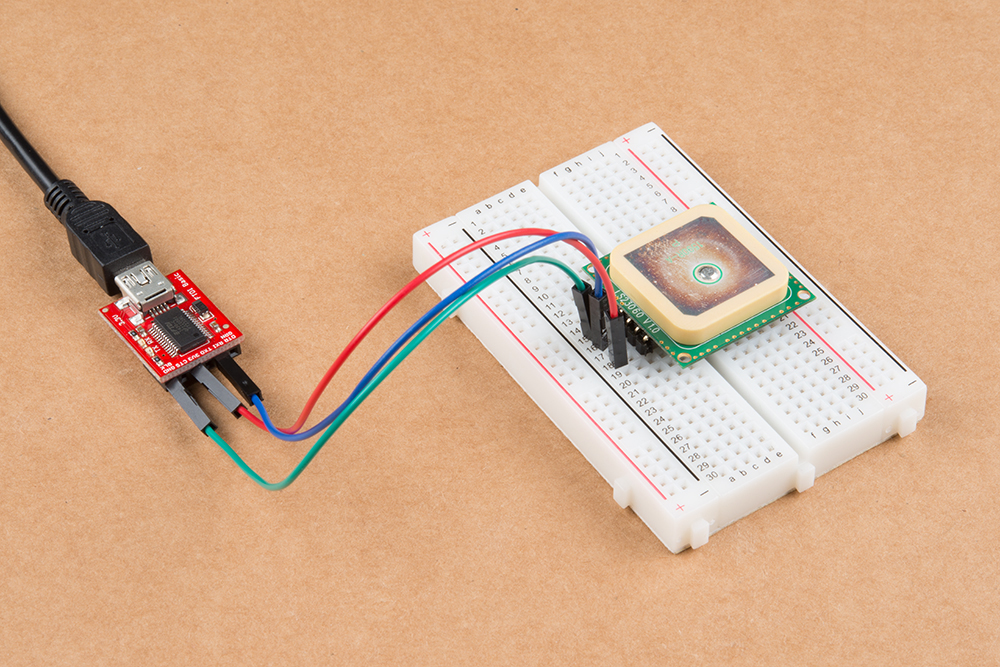
USB-to-Serial Converter
For quick tests, you can use a 3.3V usb-to-serial converter. Simply connect a 3.3V FTDI breakout board to the following pins listed below. On an FTDI, there is only one GND pin available. Connecting one GND pin is sufficient. To read the NMEA sentences, it is not necessary to connect the GPS receiver's Rx pin to the FTDI unless you are configuring the GPS receiver. For this tutorial, we will just need to connect the GPS receiver's Tx pin to the Rx of your FTDI.
| LS20031 (Top View Starting from the Left) |
3.3V FTDI Breakout Board |
|---|---|
| GND | GND |
| GND | GND |
| Tx (3.3V TTL) | Rx |
| Rx (3.3V TTL) | Tx |
| Vcc | 3.3V |
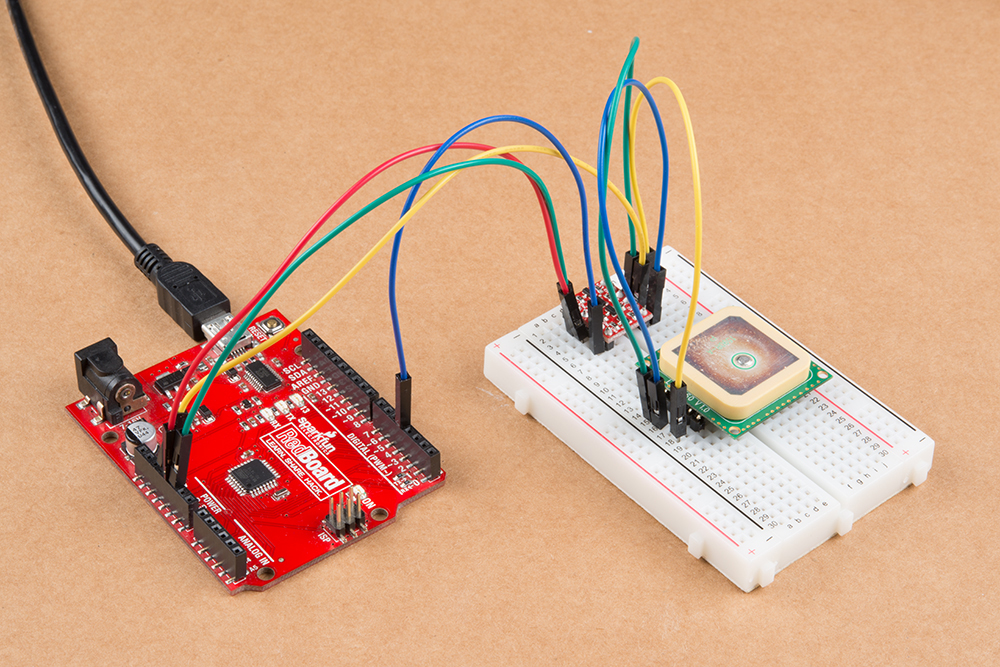
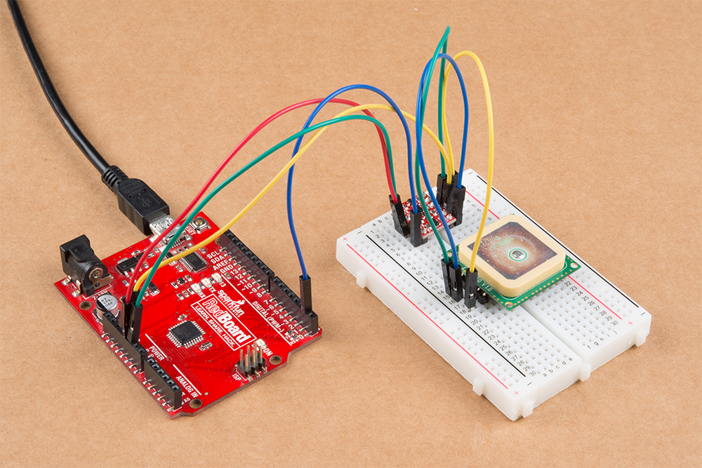
Microcontroller
In order to retrieve data from the GPS module and do anything meaningful with the data in an embedded project, we will connect it to an Arduino. The LS20031 requires 3.3V for power and according to the product pages requires 41mA of current so we can use the Arduino's 3.3V pin for power as that can supply up to 50mA. The only complication with using the module connected to a standard 5V Arduino is that the module can only communicate with a maximum of 3.3V. To safely and reliably communicate with the 5V Arduino, we will be using a logic level converter.
| LS20031 (Top View Starting from the Left) |
Logic Level Converter (Low Side) | Logic Level Converter (High Side) | Arduino Uno (Atmega328P) Pin |
|---|---|---|---|
| GND | GND | GND | GND |
| GND | GND | GND | GND |
| Tx (3.3V TTL) | LV1 | HV1 | D4 |
| Rx (3.3V TTL) (optional) |
LV4 (optional) |
HV4 (optional) |
D3 (optional) |
| Vcc | LV | 3.3V | |
| HV | 5V |
Software Library Installation
Mikal Hart has written an excellent library to parse the GPS data. Click on the button below to download the TinyGPSPlus library.
You will need to install the library via the ZIP folder. Open Arduino, navigate to Sketch > Include Library > Add .ZIP Library, and select the ZIP folder you just downloaded.
Examples
Example 1: Quick Test
For a quick test, let's connect to the LS20031 GPS receiver to view the NMEA sentences. You can use either of the two connection options below.
a.) USB-to-Serial Converter
One option is to connect a 3.3V FTDI to the LS20031 GPS receiver.
b.) Microcontroller
You can also use the USB-to-serial converter on an Arduino-compatible device as long as you configure the hardware UART pins to inputs. Once set as an input, there will not be any bus contention between the ATmega, FTDI, and the GPS receiver. Copy the code below and upload to the Arduino. In this case, we will be using a RedBoard programmed with Arduino.
language:c
/*
  SerialBridge.ino

  Written by: Mike Hord
  Date: 3/8/2013

  Description: Simple sketch to turn an Arduino-compatible device into a
  USB-to-serial bridge.

  NOTE: There is no need to include *any* Serial functions
  at all*. Doing so would only serve to override the
  pinMode() commands. The baud rate will be set by the
  computer when the serial program connects to the bridge
  device.
*/

void setup()
{
  // Make the RX/TX lines inputs, so they don't contend with
  //  the lines on the serial UART and cause data issues or damage.
  pinMode(0, INPUT);
  pinMode(1, INPUT);
}

void loop()
{
  // Nothing here, because we don't *need* anything here.
}
Then move the GPS receiver's Tx wire on the HV side of the logic level converter from pin 4 to pin 1.
Reading the NMEA Sentences
Open a serial monitor or terminal program at a baud rate of 57600. The information is displayed as NMEA sentences which the GPS module uses to communicate position information. You should see an output similar to the values below. If nothing is displayed, you'll need to double check your connections, soldering, and baud rate.
language:bash
$GPGGA,105317.709,8960.0000,N,00000.0000,E,0,0,,137.0,M,13.0,M,,*4C
$GPGLL,8960.0000,N,00000.0000,E,105317.709,V,N*49
$GPGSA,A,1,,,,,,,,,,,,,,,*1E
$GPGSV,1,1,00*79
$GPRMC,105317.709,V,8960.0000,N,00000.0000,E,0.00,0.00,010610,,,N*78
$GPVTG,0.00,T,,M,0.00,N,0.00,K,N*32
Open up the datasheet and try reading the sentences. Notice that the values between the delimiters (i.e. the commas ",") are empty? This is because the GPS receiver has not received a satellite lock yet. You will notice that the "V" is displayed on a few NMEA sentences (specifically the GPRMC sentences in the second field). This indicates that the data is invalid and there are not enough satellites in view. This should take a few seconds before you get a lock. Eventually, more fields will be filled in once the GPS receiver gathers enough information and achieves a satellite lock. You will also see a letter "A" indicating there is a valid lock.
language:bash
$GPGGA,065938.200,4005.9932,N,10509.9938,W,1,9,0.86,1562.8,M,-20.7,M,,*5C
$GPGLL,4005.9932,N,10509.9938,W,065938.200,A,A*4E
$GPGSA,A,3,17,28,30,01,13,24,15,11,06,,,,1.62,0.86,1.37*04
$GPGSV,4,1,13,17,80,265,43,28,62,054,36,19,48,235,,30,41,156,33*78
$GPGSV,4,2,13,48,35,219,29,01,33,058,25,13,28,250,41,11,22,048,29*70
$GPGSV,4,3,13,15,15,287,36,06,15,181,23,24,13,317,33,07,10,149,22*74
$GPGSV,4,4,13,22,01,079,*44
$GPRMC,065938.200,A,4005.9932,N,10509.9938,W,0.01,57.88,261118,,,A*47
$GPVTG,57.88,T,,M,0.01,N,0.01,K,A*0F
Baud rate mismatch (aka garbage) as described in this Common Pitfalls section.
Example 2: Software Serial Passthrough
This example is not as straight forward as other software serial passthroughs. When using software serial, users experienced problems with the default buffer size. To adjust the software serial library for the LS20031, you will need to head to the your Arduino's program folder. On a Windows, the path should be similar to the directory as shown below.
C:\Program Files\arduino-1.8.5\hardware\arduino\avr\libraries\SoftwareSerial\src
Open a text editing program to modify the SoftwareSerial.h file. Then look for this section of code near the top of the header:
#ifndef _SS_MAX_RX_BUFF
#define _SS_MAX_RX_BUFF 64 // RX buffer size
#endif
Adjust the buffer size of 64 by changing the value to 256 as shown below.
#ifndef _SS_MAX_RX_BUFF
#define _SS_MAX_RX_BUFF 256 // RX buffer size
#endif
Save the changes. If you have the Arduino IDE open, be sure to close it out. Open the Arduino back up (the version with the modified SoftwareSerial.h file). Copy and paste the code below. Select the Arduino board and COM port for your Arduino. Then click on upload.
language:c
/*
GPS_SerialPassthrough.ino
LS20031 GPS Receiver

By: Ho Yun "Bobby" Chan @ SparkFun Electronics
Date: November 25th, 2018

Description: This is a basic serial passthrough code that
sets up a software serial port to pass data between the a
GPS receiver and the serial monitor. This code should work
with any GPS receiver as long as you have the correct
baud rate.
*/

// We'll use SoftwareSerial to communicate with the FPS:
#include <SoftwareSerial.h>

// set up software serial pins for Arduino's w/ Atmega328P's
// GPS (TX) is connected to pin 4 (Arduino's Software RX)
// GPS (RX) is connected through a converter to pin 3 (Arduino's Software TX)
SoftwareSerial gps(4, 3); // (Arduino SS_RX = pin 4, Arduino SS_TX = pin 3)
static const uint32_t GPSBaud = 57600; //LS20031's Baud Rate

/*If using another Arduino microcontroller, please be aware of the
limitations listed in the library's note
=> https://www.arduino.cc/en/Reference/softwareSerial . Do
not forget to rewire the connection to the Arduino. if you do!*/

// GPS (TX) is connected to pin 11 (Arduino's Software RX)
// GPS (RX) is connected through a converter to pin 10 (Arduino's Software TX)
//SoftwareSerial gps(11, 10); // (Arduino SS_RX = pin 11, Arduino SS_TX = pin 10)

void setup()
{
  // Set up both ports at 115200 baud since that is the GPS's default baud.
  // Make sure the baud rate matches the config setting of SDK demo software.
  Serial.begin(115200); //set up Arduino's hardware serial UART
  gps.begin(57600);    //set up software serial UART for GPS
}

void loop()
{
  if (Serial.available())
  { // If data comes in from serial monitor, send it out to GPS
    gps.write(Serial.read());
  }
  if (gps.available())
  { // If data comes in from GPS, send it out to serial monitor
    Serial.write(gps.read());
  }
}
If you have not already, make sure to have the GPS Receiver's Tx wire on the HV side of the logic level converter on pin 4.
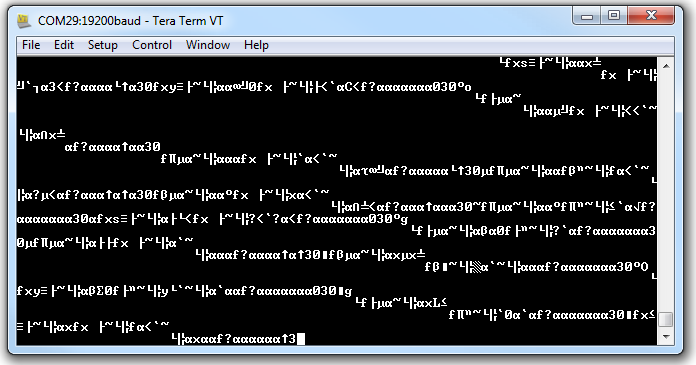
Open a serial monitor at a baud rate of 115200. You should see an output similar to the values below like example 1. Remember the values shown below are actually not valid yet because there is not a satellite lock. This should take a few seconds. If nothing is displayed, you'll need to double check your connections, soldering, and baud rate.
language:bash
$GPGGA,105317.709,8960.0000,N,00000.0000,E,0,0,,137.0,M,13.0,M,,*4C
$GPGLL,8960.0000,N,00000.0000,E,105317.709,V,N*49
$GPGSA,A,1,,,,,,,,,,,,,,,*1E
$GPGSV,1,1,00*79
$GPRMC,105317.709,V,8960.0000,N,00000.0000,E,0.00,0.00,010610,,,N*78
$GPVTG,0.00,T,,M,0.00,N,0.00,K,N*32
    $GPGGA,014646.400,4001.0409,N,10515.1451,W,2,8,0.94,1614.5,M,-20.6,M,0000,0000*5A
    $GPGLL,4001.0409,N,10515.1451,W,016640,D4
    GGAM,2,020,30,82,,1600412*
    $GGV3,13,01420,9,02,6709,703,8,5*
    $PS,2,173,1,,0,41,42,0072,,6,93*2
    PSV3313,9211,2210,78,*6$PRC0664,A40.4,,51541W.217.061,,D7
    $VG1.5,,M.2N0.,,*
Example 3: TinyGPSPlusPlus - DeviceExample.ino
With the TinyGPS++ Arduino Library installed, open the Arduino IDE. Open the example DeviceExample.ino by clicking on File > Examples > TinyGPS++ > DeviceExample. Once open, update software serial's baud rate to 56700 by modifying this line of code from:
language:c
static const uint32_t GPSBaud = 4800;
to
language:c
static const uint32_t GPSBaud = 57600;
Select the correct board definition and COM port. Make sure that your the the GPS receiver's output is connected to pin 4. Then open the serial monitor. The example code outputs a different baud rate to your computer's serial port so make sure that set at 115200. Your output should look similar to the reading below when there is a lock.

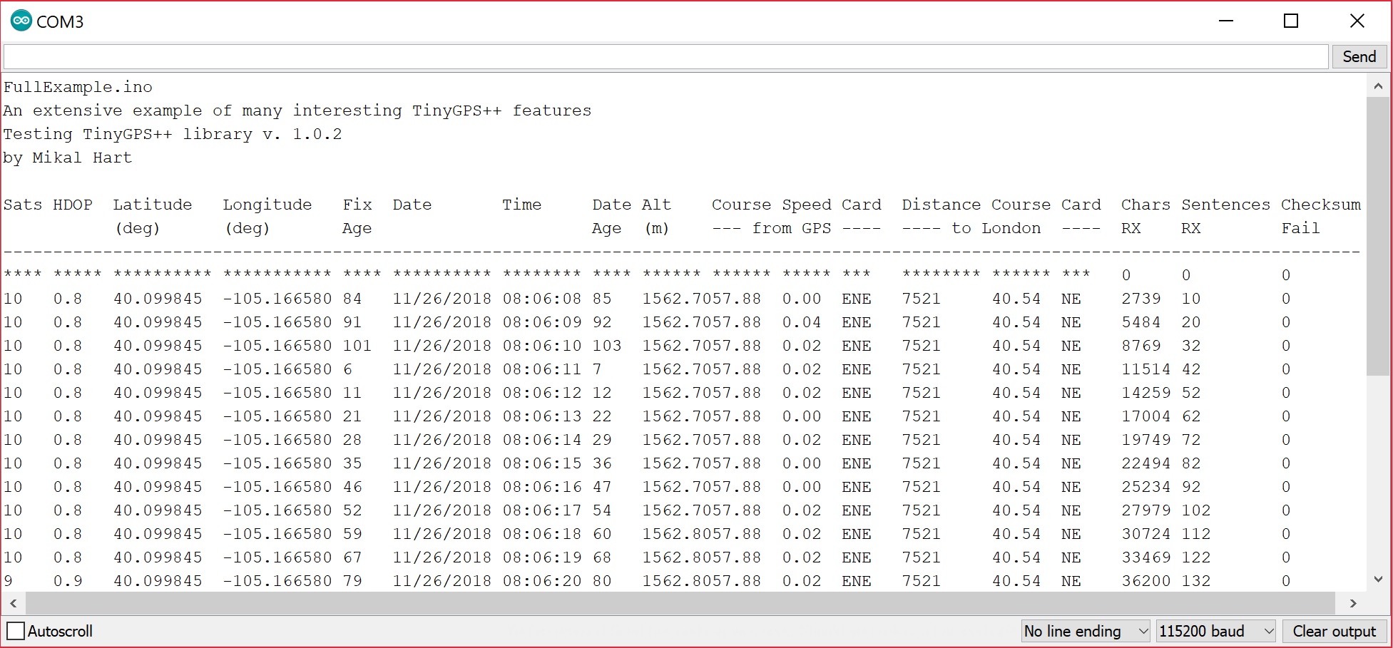
Example 4: TinyGPSPlusPlus - FullExample.ino
With the TinyGPS++ Arduino Library installed, open the Arduino IDE. Open the example FullExample.ino by clicking on File > Examples > TinyGPS++ > FullExample. You will also need to update the software serial's baud rate by setting it to 56700. Modify this line of code from:
language:c
static const uint32_t GPSBaud = 4800;
to
language:c
static const uint32_t GPSBaud = 57600;
Select the correct board definition and COM port. Again, make sure that your the the GPS receiver's output is connected to pin 4. Then open the serial monitor. The example code outputs a different baud rate to your computer's serial port so make sure that set at 115200. Your output should look similar to the reading below when there is a lock.
Moar Examples!
If you check out the TinyGPSPlus examples folder, you will notice that there are more examples listed in the TinyGPSPlus library! Browse through the code, adjust as necessary when testing the examples before applying it to your next project!
Troubleshooting
Below are a few additional troubleshooting tips and tricks when using the LS20031 GPS receiver.
1.) GPS Lock Problems With No Satellites in View
If there are no satellites in view, try moving to a different location. Using any GPS receiver inside a building makes it difficult to get a GPS lock. This also applies to locations with objects (i.e. urban canyons) that can block the GPS receiver's view to satellites.
2.) GPS Lock Problems With Satellites in View
If your unit can see 4+ satellites but never gets a fix/lock, try sending a FULL_COLD_RESTART. A user a problem where the unit would report that it could see up to 9 satellites (the "09" in the below GSV sentences):
$GPGSV,3,1,09,05,,,39,29,,,31,26,,,42,02,,,38*7F
$GPGSV,3,2,09,21,,,20,15,,,18,30,,,29,10,,,24*72
$GPGSV,3,3,09,07,,,25*70
While the GPS could see 9 satellites, it never started producing position data / blinking the red LED. Try sending the following command. You will need to connect to the GPS receiver's Rx pin.
Serial.println("$PMTK104*37"); // FULL COLD RESTART
Details are listed in the MTK NMEA Packet User Manual. This resets the GPS's almanac, which very rarely comes with bad data. If you are using the older TinyGPS library, it only uses GGA and RMC sentences. Therefore, you could configure your unit to only send those values, and only once every 5 fixes (that is, 1Hz) using the following command:
Serial.println("$PMTK314,0,5,0,5,0,0,0,0,0,0,0,0,0,0,0,0,0*28");
3.) No Output When Using Examples in the TinyGPSPlus Library
The examples in the TinyGPSPlus Library require a satellite lock in order to view the parsed data. Try viewing the output using an FTDI to see if the GPS receiver is outputting NMEA sentences. If you are able to view NMEA sentences then the LS20031 is functional. You will probably just need to move to a different location to achieve a satellite lock or reset the GPS receiver as explained above.
Resources and Going Further
Now that you've successfully got your LS20031 GPS receiver up and running, it's time to incorporate it into your own project!
For more information, check out the resources below:
- Datasheet (PDF)
- PMTK Protocol Reference (PDF)
- Mini GPS (ZIP) - Great configuration software
- Dallas Maker Space Wiki: LS20031
- MTK NMEA Checksum Calculator - This is a simple calculator to compute the checksum field for the MediaTek / ETEK chipset's command extensions to the NMEA protocol.
- Projects
- Example Configuration from DIYDrones
- Parsing GPS with FPGA - GPS to 16x2 Character LCD Using an FPGA example
- Wayne's Tinkering Page: Navigating with GPS - Example using the LS20031 for the SparkFun AVC
Need some inspiration for your next project? Check out some of these related tutorials: