LSM303C 6DoF Hookup Guide
 .Brent.
Hardware Assembly
I2C Example
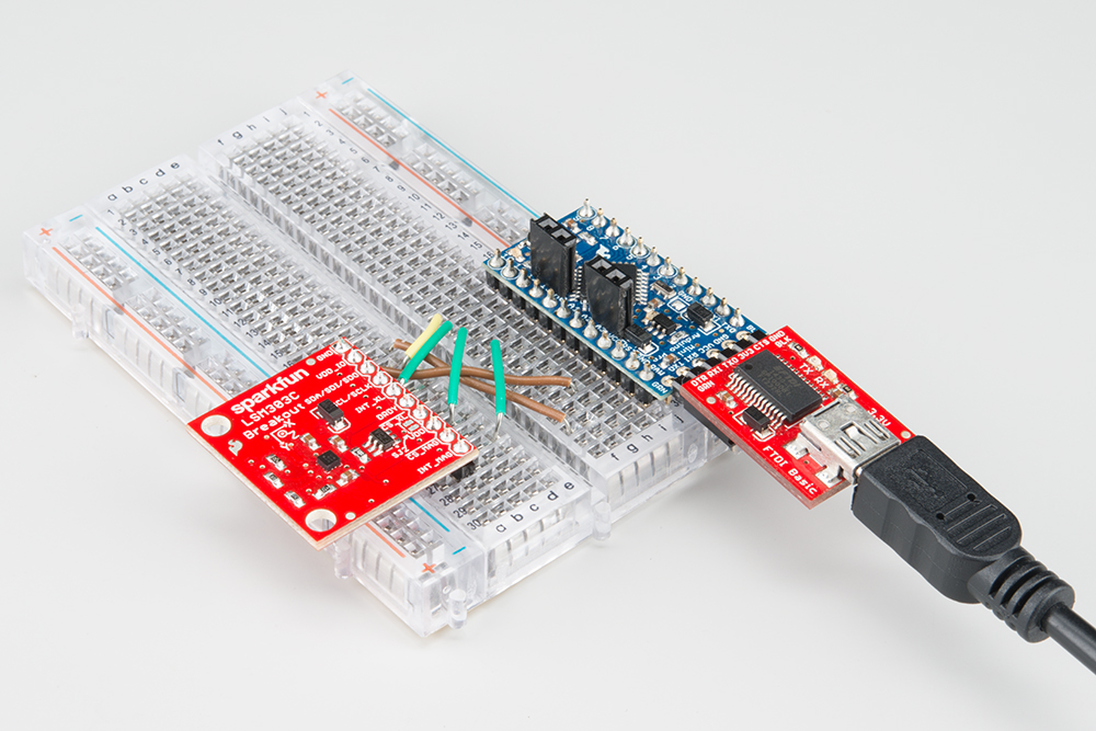
The basic use case for the LSM303C requires 4 connections to the µController or µProcessor; power, ground, I2C clock and data. The following images shows how we used a SparkFun FTDI Basic Breakout, and an 3.3V Arduino Pro Mini to power and interface to a LSM303C 6 DOF Breakout board.
Make connections to the breakout anyway that makes you happy. The board in the above photo has a straight header soldered to it. We could have used a right angle header, or wire, etc. Please note that different mounting orientations will alter the orientation of the axes. Make sure your code matches the physical orientation for your projects.
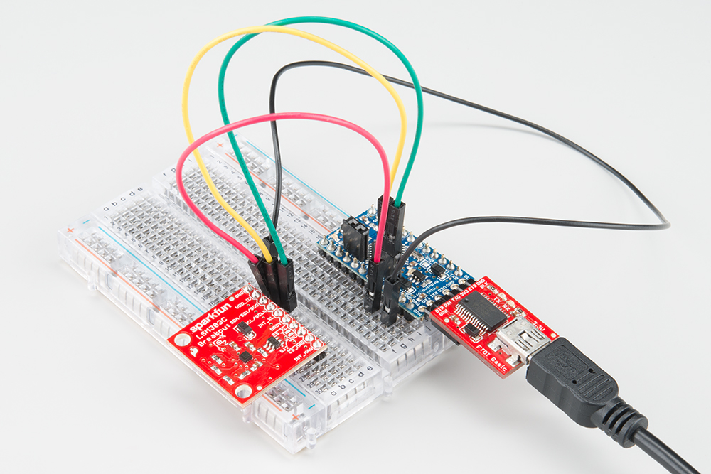
For this demo, we made the following connections:
| Arduino Pro Mini | LSM303C Breakout | Notes |
|---|---|---|
| VCC | VDD | +3.3V |
| GND | GND | +0V |
| SDA | SDA/SDI/SDO | Serial data @ +3.3V CMOS logic |
| SCL | SCL/SCLK | Serial clock @ +3.3V CMOS logic |
The whole system in our testing was powered via USB through the FTDI basic.

SPI Example
Four hardware changes need to be made to interface the sensor using SPI. Move the SDA/SDI/SDO connection from SDA on the Arduino Pro Mini to digital pin 10, move the SCK/SCLK connection from SCL on the Arduino Pro Mini to digital pin 11, and add the two chip select lines.
| Arduino Pro Mini | LSM303C Breakout | Notes |
|---|---|---|
| VCC | VDD | +3.3V |
| GND | GND | +0V |
| Digital 10 | SDA/SDI/SDO | Serial data @ +3.3V CMOS logic |
| Digital 11 | SCL/SCLK | Serial clock @ +3.3V CMOS logic |
| Digital 12 | CS_XL | Accelerometer chip select @ +3.3V CMOS logic |
| Digital 13 | CS_MAG | Magnetometer chip select @ +3.3V CMOS logic |