LSM9DS0 Hookup Guide
 jimblom
Basic Arduino Example
This example will show you how to download and install the SFE_LSM9DS0 library, and use it in it's most basic form. We'll use I2C and ignore the interrupts, which means we'll be using as few wires and Arduino pins as possible.
Download and Install the Library
We've written a full-featured Arduino library to help make interfacing with the LSM9DS0's gyro and accelerometer/magnetometer as easy-as-possible. Visit the GitHub repository to download the most recent version of the library, or click the link below:
For help installing the library, check out our How To Install An Arduino Library tutorial. You'll need to move the SFE_LSM9DS0 folder into a libraries folder within your Arduino sketchbook.
Simple Hardware Hookup (I2C)
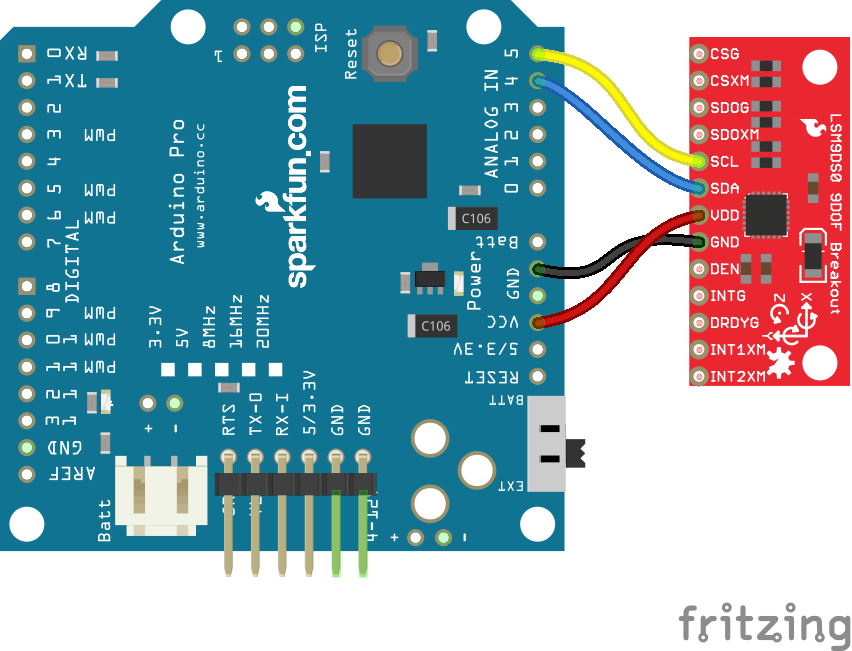
The library will work with either I2C or SPI. Since we're trying to be as frugal with our Arduino pins as possible, I2C it is! Here's a fritzing diagram for this example:

This hookup relies on all of the jumpers on the back of the board being set (as they should be, unless they've been sliced). If the jumpers have been disconnected, connect all four CS and SDO pins to 3.3V.
Since we're using I2C all we have to do is connect SDA to SDA and SCL to SCL. Unfortunately, since the LSM9DS0's maximum operating voltage is 3.6V, we need to use a level shifting board to switch between 3.3V and 5V.
Alternatively, if you have a 3.3V-operating Arduino -- like the 3.3V/8MHz Pro -- you can connect SDA and SCL directly from microcontroller to sensor.
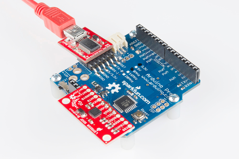
Heck, you can even mount the breakout board on top of the Arduino Pro. If you do this, you'll need to set A3 HIGH and A2 LOW. The sensor pulls little enough current that the Arduino's I/O pins can power it!
Open the LSM9DS0_Simple Example
Once you've installed the library, open Arduino (or restart it if it was already open). You'll find this first example under the File > Examples > SFE_LSM9DS0 > LSM9DS0_Simple:
language:c
/*****************************************************************
LSM9DS0_Simple.ino
SFE_LSM9DS0 Library Simple Example Code
Jim Lindblom @ SparkFun Electronics
Original Creation Date: February 18, 2014
https://github.com/sparkfun/LSM9DS0_Breakout

The LSM9DS0 is a versatile 9DOF sensor. It has a built-in
accelerometer, gyroscope, and magnetometer. Very cool! Plus it
functions over either SPI or I2C.

This Arduino sketch is a demo of the simple side of the
SFE_LSM9DS0 library. It'll demo the following:
* How to create a LSM9DS0 object, using a constructor (global
  variables section).
* How to use the begin() function of the LSM9DS0 class.
* How to read the gyroscope, accelerometer, and magnetometer
  using the readGryo(), readAccel(), readMag() functions and the
  gx, gy, gz, ax, ay, az, mx, my, and mz variables.
* How to calculate actual acceleration, rotation speed, magnetic
  field strength using the calcAccel(), calcGyro() and calcMag()
  functions.
* How to use the data from the LSM9DS0 to calculate orientation
  and heading.

Hardware setup: This library supports communicating with the
LSM9DS0 over either I2C or SPI. If you're using I2C, these are
the only connections that need to be made:
    LSM9DS0 --------- Arduino
     SCL ---------- SCL (A5 on older 'Duinos')
     SDA ---------- SDA (A4 on older 'Duinos')
     VDD ------------- 3.3V
     GND ------------- GND
(CSG, CSXM, SDOG, and SDOXM should all be pulled high jumpers on
  the breakout board will do this for you.)

If you're using SPI, here is an example hardware setup:
    LSM9DS0 --------- Arduino
          CSG -------------- 9
          CSXM ------------- 10
          SDOG ------------- 12
          SDOXM ------------ 12 (tied to SDOG)
          SCL -------------- 13
          SDA -------------- 11
          VDD -------------- 3.3V
          GND -------------- GND

The LSM9DS0 has a maximum voltage of 3.6V. Make sure you power it
off the 3.3V rail! And either use level shifters between SCL
and SDA or just use a 3.3V Arduino Pro.

Development environment specifics:
    IDE: Arduino 1.0.5
    Hardware Platform: Arduino Pro 3.3V/8MHz
    LSM9DS0 Breakout Version: 1.0

This code is beerware. If you see me (or any other SparkFun
employee) at the local, and you've found our code helpful, please
buy us a round!

Distributed as-is; no warranty is given.
*****************************************************************/

// The SFE_LSM9DS0 requires both the SPI and Wire libraries.
// Unfortunately, you'll need to include both in the Arduino
// sketch, before including the SFE_LSM9DS0 library.
#include <SPI.h> // Included for SFE_LSM9DS0 library
#include <Wire.h>
#include <SFE_LSM9DS0.h>

///////////////////////
// Example I2C Setup //
///////////////////////
// Comment out this section if you're using SPI
// SDO_XM and SDO_G are both grounded, so our addresses are:
#define LSM9DS0_XM  0x1D // Would be 0x1E if SDO_XM is LOW
#define LSM9DS0_G   0x6B // Would be 0x6A if SDO_G is LOW
// Create an instance of the LSM9DS0 library called `dof` the
// parameters for this constructor are:
// [SPI or I2C Mode declaration],[gyro I2C address],[xm I2C add.]
LSM9DS0 dof(MODE_I2C, LSM9DS0_G, LSM9DS0_XM);

///////////////////////
// Example SPI Setup //
///////////////////////
/* // Uncomment this section if you're using SPI
#define LSM9DS0_CSG  9  // CSG connected to Arduino pin 9
#define LSM9DS0_CSXM 10 // CSXM connected to Arduino pin 10
LSM9DS0 dof(MODE_SPI, LSM9DS0_CSG, LSM9DS0_CSXM);
*/

// Do you want to print calculated values or raw ADC ticks read
// from the sensor? Comment out ONE of the two #defines below
// to pick:
#define PRINT_CALCULATED
//#define PRINT_RAW

#define PRINT_SPEED 500 // 500 ms between prints

void setup()
{
  Serial.begin(115200); // Start serial at 115200 bps
  // Use the begin() function to initialize the LSM9DS0 library.
  // You can either call it with no parameters (the easy way):
  uint16_t status = dof.begin();
  // Or call it with declarations for sensor scales and data rates:
  //uint16_t status = dof.begin(dof.G_SCALE_2000DPS,
  //                            dof.A_SCALE_6G, dof.M_SCALE_2GS);

  // begin() returns a 16-bit value which includes both the gyro
  // and accelerometers WHO_AM_I response. You can check this to
  // make sure communication was successful.
  Serial.print("LSM9DS0 WHO_AM_I's returned: 0x");
  Serial.println(status, HEX);
  Serial.println("Should be 0x49D4");
  Serial.println();
}

void loop()
{
  printGyro();  // Print "G: gx, gy, gz"
  printAccel(); // Print "A: ax, ay, az"
  printMag();   // Print "M: mx, my, mz"

  // Print the heading and orientation for fun!
  printHeading((float) dof.mx, (float) dof.my);
  printOrientation(dof.calcAccel(dof.ax), dof.calcAccel(dof.ay),
                   dof.calcAccel(dof.az));
  Serial.println();

  delay(PRINT_SPEED);
}

void printGyro()
{
  // To read from the gyroscope, you must first call the
  // readGyro() function. When this exits, it'll update the
  // gx, gy, and gz variables with the most current data.
  dof.readGyro();

  // Now we can use the gx, gy, and gz variables as we please.
  // Either print them as raw ADC values, or calculated in DPS.
  Serial.print("G: ");
#ifdef PRINT_CALCULATED
  // If you want to print calculated values, you can use the
  // calcGyro helper function to convert a raw ADC value to
  // DPS. Give the function the value that you want to convert.
  Serial.print(dof.calcGyro(dof.gx), 2);
  Serial.print(", ");
  Serial.print(dof.calcGyro(dof.gy), 2);
  Serial.print(", ");
  Serial.println(dof.calcGyro(dof.gz), 2);
#elif defined PRINT_RAW
  Serial.print(dof.gx);
  Serial.print(", ");
  Serial.print(dof.gy);
  Serial.print(", ");
  Serial.println(dof.gz);
#endif
}

void printAccel()
{
  // To read from the accelerometer, you must first call the
  // readAccel() function. When this exits, it'll update the
  // ax, ay, and az variables with the most current data.
  dof.readAccel();

  // Now we can use the ax, ay, and az variables as we please.
  // Either print them as raw ADC values, or calculated in g's.
  Serial.print("A: ");
#ifdef PRINT_CALCULATED
  // If you want to print calculated values, you can use the
  // calcAccel helper function to convert a raw ADC value to
  // g's. Give the function the value that you want to convert.
  Serial.print(dof.calcAccel(dof.ax), 2);
  Serial.print(", ");
  Serial.print(dof.calcAccel(dof.ay), 2);
  Serial.print(", ");
  Serial.println(dof.calcAccel(dof.az), 2);
#elif defined PRINT_RAW
  Serial.print(dof.ax);
  Serial.print(", ");
  Serial.print(dof.ay);
  Serial.print(", ");
  Serial.println(dof.az);
#endif

}

void printMag()
{
  // To read from the magnetometer, you must first call the
  // readMag() function. When this exits, it'll update the
  // mx, my, and mz variables with the most current data.
  dof.readMag();

  // Now we can use the mx, my, and mz variables as we please.
  // Either print them as raw ADC values, or calculated in Gauss.
  Serial.print("M: ");
#ifdef PRINT_CALCULATED
  // If you want to print calculated values, you can use the
  // calcMag helper function to convert a raw ADC value to
  // Gauss. Give the function the value that you want to convert.
  Serial.print(dof.calcMag(dof.mx), 2);
  Serial.print(", ");
  Serial.print(dof.calcMag(dof.my), 2);
  Serial.print(", ");
  Serial.println(dof.calcMag(dof.mz), 2);
#elif defined PRINT_RAW
  Serial.print(dof.mx);
  Serial.print(", ");
  Serial.print(dof.my);
  Serial.print(", ");
  Serial.println(dof.mz);
#endif
}

// Here's a fun function to calculate your heading, using Earth's
// magnetic field.
// It only works if the sensor is flat (z-axis normal to Earth).
// Additionally, you may need to add or subtract a declination
// angle to get the heading normalized to your location.
// See: http://www.ngdc.noaa.gov/geomag/declination.shtml
void printHeading(float hx, float hy)
{
  float heading;

  if (hy > 0)
  {
    heading = 90 - (atan(hx / hy) * (180 / PI));
  }
  else if (hy < 0)
  {
    heading = - (atan(hx / hy) * (180 / PI));
  }
  else // hy = 0
  {
    if (hx < 0) heading = 180;
    else heading = 0;
  }

  Serial.print("Heading: ");
  Serial.println(heading, 2);
}

// Another fun function that does calculations based on the
// acclerometer data. This function will print your LSM9DS0's
// orientation -- it's roll and pitch angles.
void printOrientation(float x, float y, float z)
{
  float pitch, roll;

  pitch = atan2(x, sqrt(y * y) + (z * z));
  roll = atan2(y, sqrt(x * x) + (z * z));
  pitch *= 180.0 / PI;
  roll *= 180.0 / PI;

  Serial.print("Pitch, Roll: ");
  Serial.print(pitch, 2);
  Serial.print(", ");
  Serial.println(roll, 2);
}
After uploading the code, open up your serial monitor and set the baud rate to 115200 bps. You should see something like this begin to stream by:
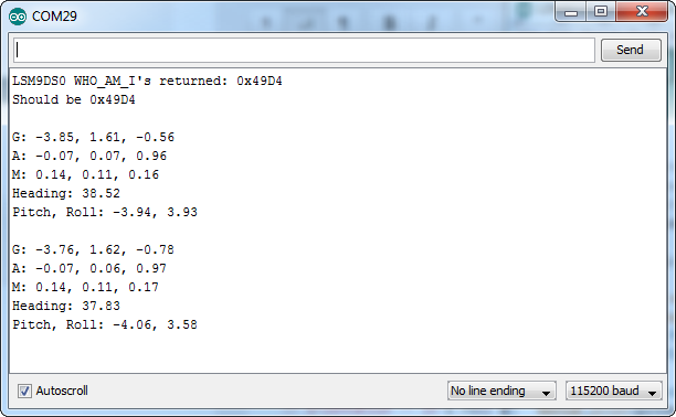
Each serial output blurb spits out the readings from all nine dimensions of movement. First the gyroscope readings ("G: x, y, z") in degrees per second (DPS). Then come three degrees of acceleration in g's ("A: x, y, z"), followed by the magnetic field readings ("M: x, y, z") in gauss (Gs).
Try moving your breadboard around (carefully, don't disconnect any wires!). Are the numbers changing? Check out the acceleration values -- the axis normal to gravity should feel about 1 g of acceleration on it.
Does the heading output what you'd expect? If north seems a few degrees off, you may need to adjust for your declination. That means adding or subtracting a constant number that correlates to your location on this map.
That's all there is to it! If you want to get more out of the LSM9DS0 by using the interrupt outputs, check out the next page! Or check out the Using the Arduino Library Page for help using the library.