LSM9DS1 Breakout Hookup Guide
 jimblom
Hardware Hookup
The LSM9DS1 will work over either I2C or SPI. Here are some example wiring diagrams, demonstrating how to wire up each interface.
I2C Hardware Hookup
Out-of-the-box, the board is configured for an I2C interface, as such we recommend using this hookup if you're otherwise agnostic. All you need is four wires!
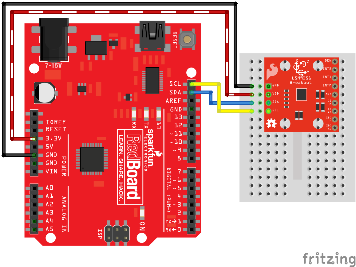
This hookup relies on all of the jumpers on the back of the board being set (as they should be, unless they've been sliced). If the jumpers have been cut, connect all four CS and SDO pins to 3.3V.
No level shifters even though the Arduino's I/O pins are 5V? Well, I2C is a funny interface: pins aren't directly pulled high by a GPIO, instead an open-drain MOSFET relies on pull-up resistors to create a logic high. Because the breakout board pull-up resistors are stronger (less resistance) than the Arduino's internal pull-ups, the voltage on the logic pins will be much closer to 3.3V (though a little higher) than 5V -- within a tolerable range. Just make sure you power the breakout off of the Arduino's 3.3V power rail!
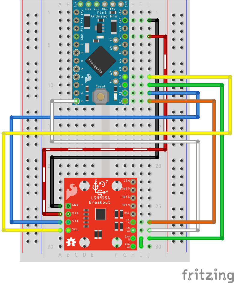
SPI Hardware Hookup
For the SPI hookup, we'll use the Arduino's hardware SPI pins -- 11 (MOSI), 12 (MISO), and 13 (SCLK) -- in addition to two digital pins of your choice (for the chip selects).
3.3V Arduino w/ SPI
If you're using a 3.3V Arduino, like the 3.3V/8MHz Pro Mini, you can hook the microcontroller pins directly up to the LSM9DS1.
5V Arduino w/ SPI
If you're using a 5V Arduino, you'll also need to grab a level shifter to keep the SPI signals within the tolerable voltage range. You could use the SparkFun Bi-Directional Logic Level Converter for example:
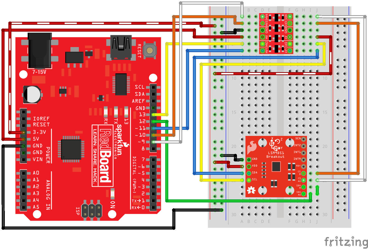
(Unless you enjoy wire-tangles, the I2C or 3.3V SPI hookups are recommended.)