LTE GNSS Breakout - SARA-R5 Hookup Guide
 El Duderino,
  PaulZC
 Introduction
The SparkFun LTE GNSS Breakout - SARA-R5 provides a robust development tool for the SARA-R510M8S LTE-M module from u-blox.
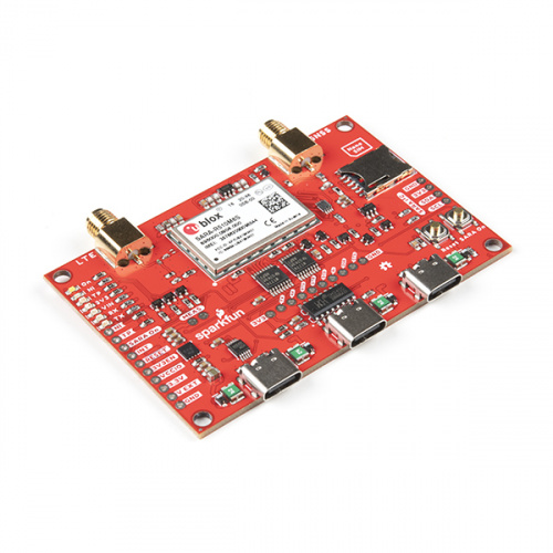
The u-blox SARA-R510M8S module is a secure cloud LTE Cat M1, LTE Cat NB2 solution based on u-blox's UBX-R5 cellular chipset with an integrated u-blox M8 GNSS receiver chip and separate GNSS antenna interface. This breakout routes all of the functional pins on the R510M8S module to user interfaces (USB or plated-through hole) so you can take full advantage of all of the features available on this impressive LTE/GNSS module.
The SARA-R5's UART interface can be configured into one of five variants, providing connectivity over one or two UARTs. A separate USB port provides access to the SARA's trace log for diagnostic purposes. This breakout provides access to all three serial interfaces (UART1, UART2 and SARA Diag) via separate USB-C connections. All eight 3.3V serial signals are available on a 0.1"-pitch breakout header.
The breakout ships with a Hologram SIM card. If you prefer to use your own SIM card, please check that your chosen service provider offers LTE-M coverage for your area before purchasing.
Required Materials
In order to follow along with this tutorial you'll need the following items to use with the LTE GNSS Breakout - SARA-R5.
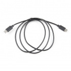
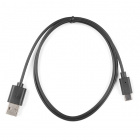
The primary interface for this breakout is over USB-C so you'll need at least one USB-C cable:


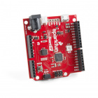
For those who prefer to use the LTE GNSS Breakout with our u-blox SARA-R5 Arduino Library, you'll need an Arduino development board:


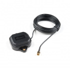
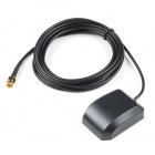
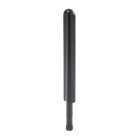
The breakout requires a pair of antennas, one for the LTE module and another for the GNSS receiver. The options below work with the LTE GNSS Breakout:
Suggested Reading
If you aren't familiar with the following concepts you may want to check out these tutorials before continuing.
How to Solder: Through-Hole Soldering
Serial Communication
Installing an Arduino Library
Hardware Overview
Let's take a closer look at the SARA-R510M8S module and other features of the SparkFun LTE GNSS Breakout - SARA-R5.
u-blox SARA-R510M8S
The SARA-R510M8S module from u-blox combines u-blox's UBX-R5 cellular chipset with their M8 GNSS receiver chipset to provide a 5G-Ready wireless IoT device complete with positioning data all on a single chip. For a thorough overview of the SARA-R5 modules, please review the SARA-R5 datasheet.

The u-blox UBX-R5 chipset boasts some impressive features including:
- Multi-region LTE M1 and NB2 Half-Duplex.
- Built-in end-to-end security with hardware-based root of trust inside a discrete secure element.
- A full security suite with foundation, design, end-to-end security as well as access control.
- Over-the-air cirital firmware updates and services enabled via the uFOTA client/server solution.
- Optimized for ultra-low power consumption.
The built-in u‑blox M8 GNSS receiver provides accurate and reliable positioning with a separate GNSS antenna interface for an external antenna. The GNSS position data is enhanced with u-blox's CellLocate® data. The receiver outputs data in NMEA format which can be parsed through our u-blox SARA-R5 Arduino Library.
The SARA-R5 supports many different forms of data communication from full TCP/IP sockets and packet switched data, through HTTP Get/Put/Post, FTP (the SARA has a built-in file system), Ping, to good old SMS text messaging!
The board also includes the necessary SMA connectors for external GNSS and LTE antennas as well as a nano SIM card slot.
SARA-R5 UARTs and USB-C Connectors
The LTE GNSS Breakout has three USB-C connectors on board to provide power or interact with the module's two hardware UARTs as well as the SARA Diagnostic port to access the SARA's trace log1. The UART data for both the UART1 and UART2 USB-C connectors is translated to USB data through a CH340C USB-to-Serial adapter IC.
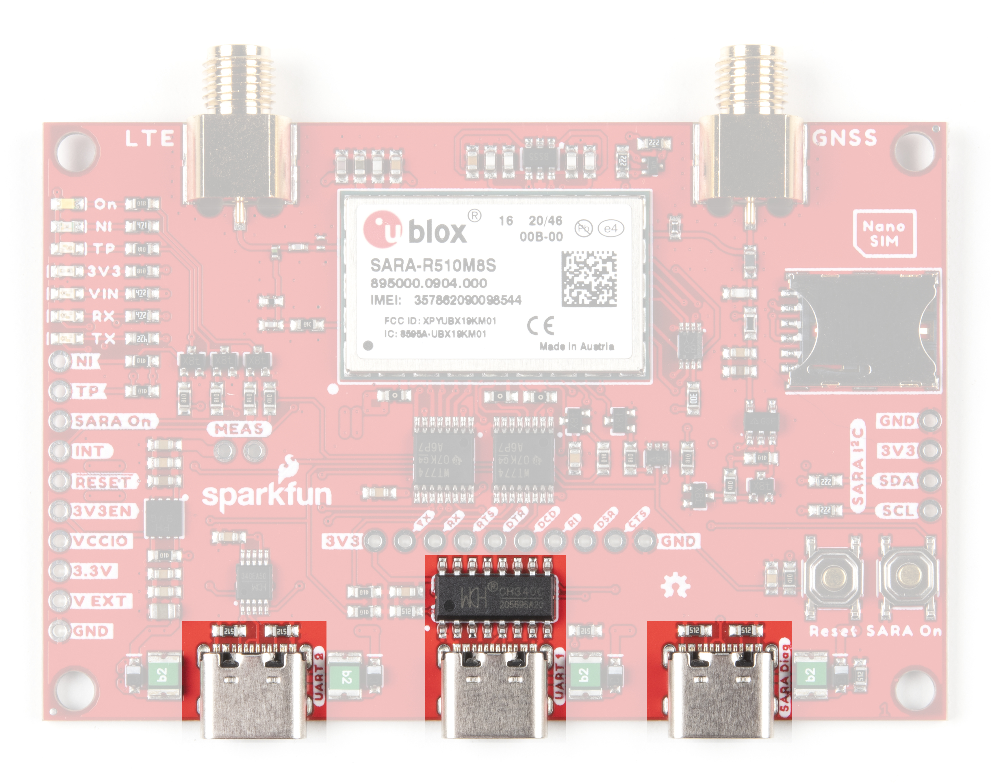
The breakout comes pre-configured to support a single UART interface (either Variant 0 or Variant 1). Enable any of the dual UART interfaces (Variants 2-4) by adjusting several jumpers on the board (refer to section 2.5.1 of the SARA-R5 datasheet and section 1.9.1. of the SARA-R5 System Integration Manual for more information on the UART variants). Read on to the Hardware Assembly section for detailed instructions on how to configure the breakout to use the dual UART variants.
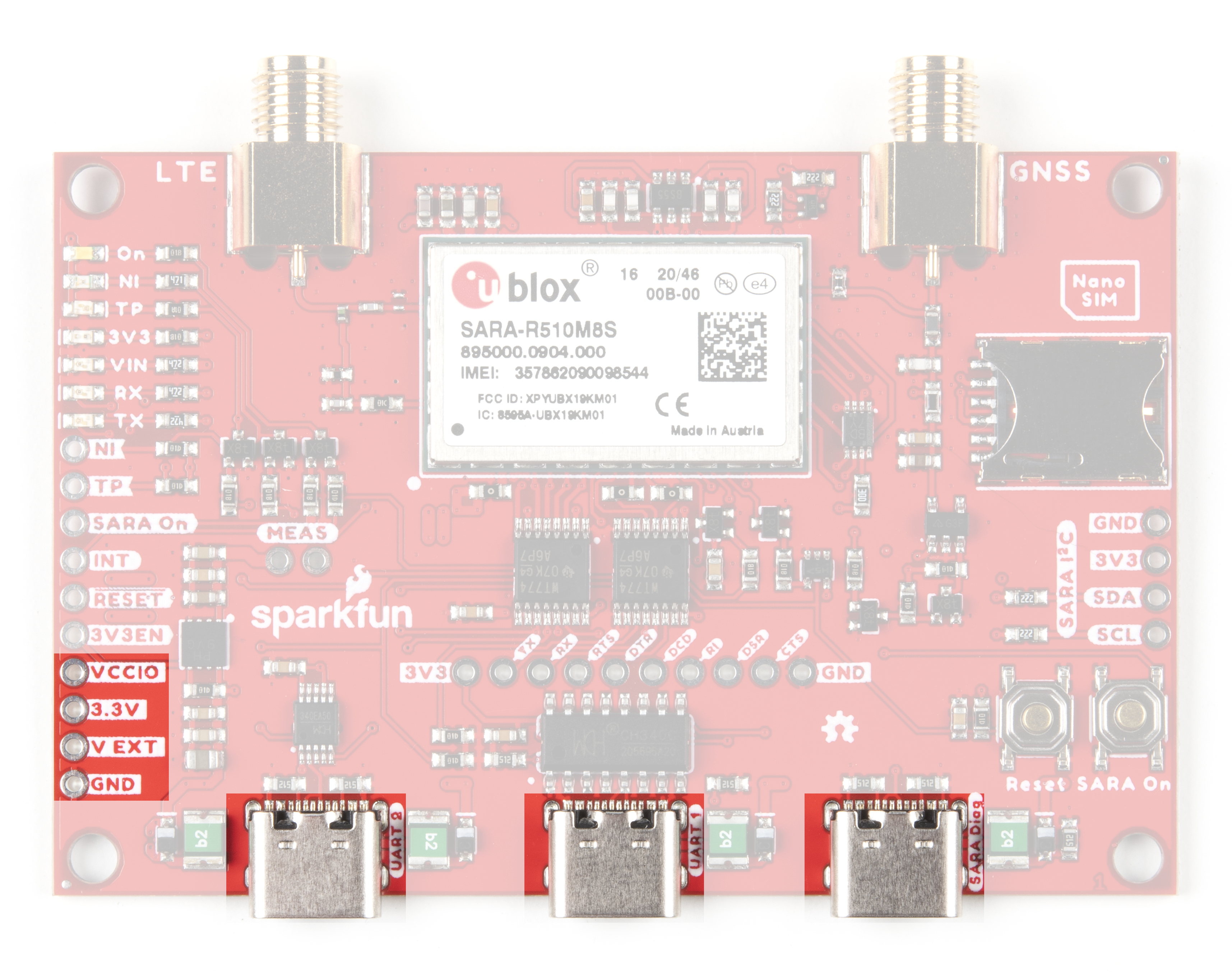
Power Supply
The LTE GNSS Breakout is designed to accept power either over USB-C or the dedicated power pin, V EXT. The V EXT pin feeds into the 3.3V regulator which accepts a supply voltage between 3.7V to 6.0V. u-blox designed the SARA-R510M8S to be power-efficient with a variety of low-power and sleep modes and pulls a max of 395mA during transmission (Tx).
Plated Through Hole (PTH) Interfaces
As expected with a breakout, we've routed nearly all functional pins from the SARA-R510M8S to plated through-hole (PTH) headers for users to directly interact with them. We've already covered the power PTHs so let's take a look at the other pins on the LTE GNSS Breakout.
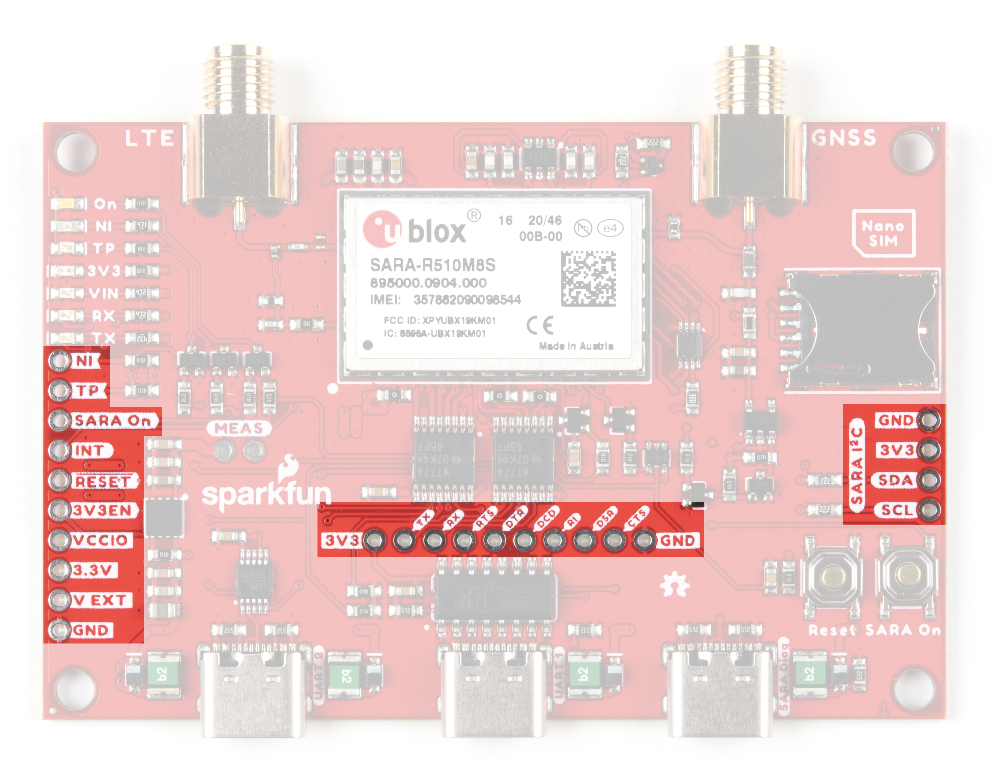
UART PTHs
In the center of the board you'll find the Serial UART PTH header. This header is normally netted to the UART1 USB-C connector through a CH340 serial converter IC for single-UART operation. You can isolate any of the pins to directly interact with them by opening the jumpers on the bottom of the board (more on that in the following "Solder Jumpers" section).
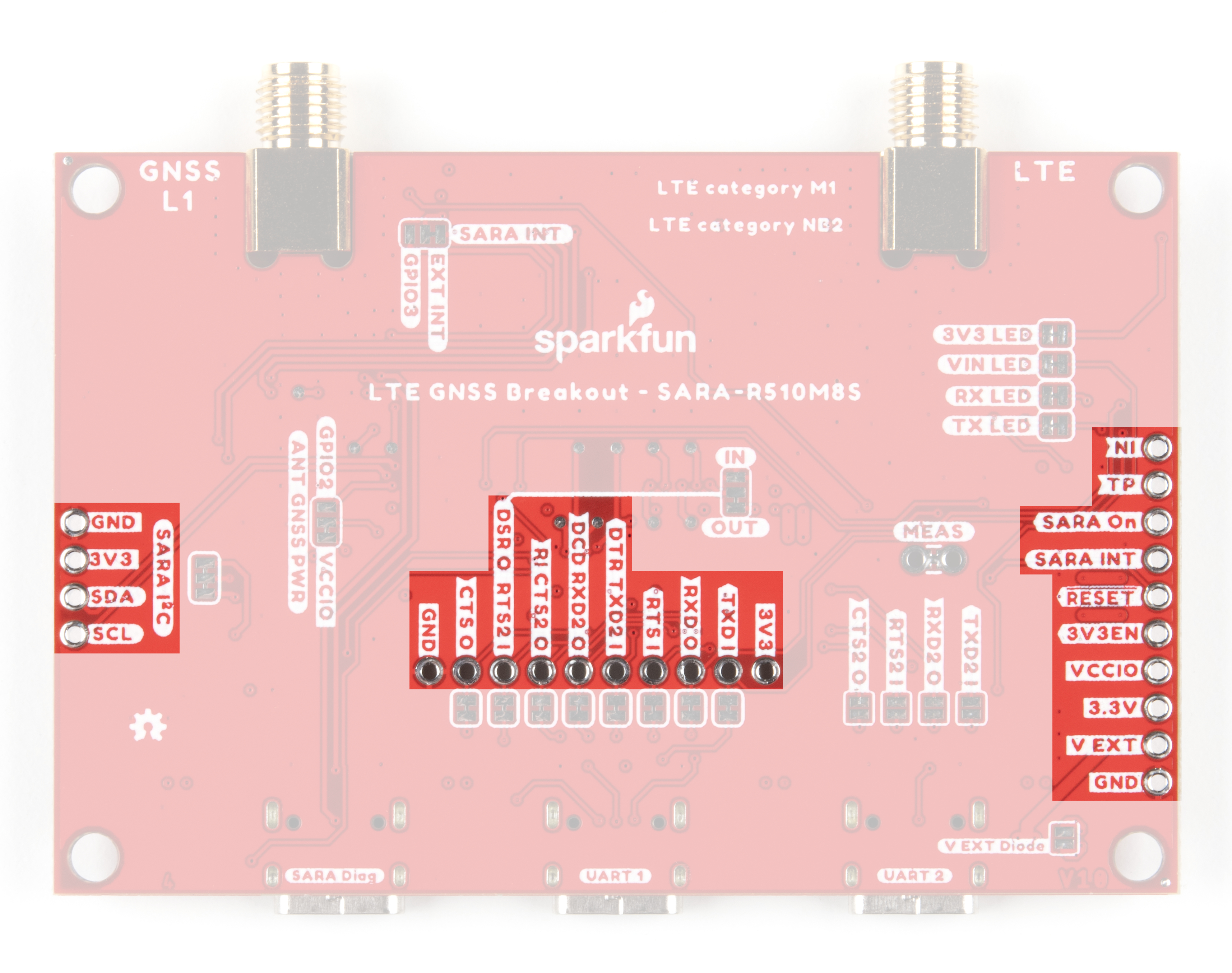
The behavior of some of the pins on this header change depending on whether the SARA-R5 is in single or dual-UART mode. The table below outlines their functionality when in either UART mode. Read on to the Hardware Assembly section for instructions on how to enable the UART2 USB-C connection.
| UART Header Pin Label | Single UART Behavior | Dual UART Behavior |
|---|---|---|
| 3V3 | 3.3V Out | |
| TXD I | UART1 Serial Data Input | |
| RXD O | UART1 Serial Data Output | |
| RTS I | UART1 Request to Send Input | |
| DTR / TXD2 I | Data Terminal Ready | UART2 Serial data input |
| DCD / RXD2 O | Data Carrier Detect | UART2 Serial data |
| RI / CTS2 O | Ring Indicator | UART2 Clear to Send Output |
| DSR O / RTS2 I | Data Set Ready Output | UART2 Request to Send Input |
| CTS O | UART1 Clear to Send Output | |
| GND | Ground | |
Take note these pins are level shifted from the SARA-R5's 1.8V logic to 3.3V logic for the PTHs and 5V logic for USB. Modify the board to isoloate these signals and connect them to an Arduino development board to use this breakout with the SparkFun u-blox SARA-R5 Arduino Library. Read on to the Hardware Assembly and Arduino Library/Example sections for more information on using the board with the u-blox SARA-R5 Arduino library.
Additional GPIO PTHs
The board routes the pins for the SARA-R5 I2C bus to a labeled PTH header on one side of the board. On the other side, the SARA On, SARA External Interrupt, Reset and 3V3 Enable pins are broken out along with indicator outputs for Time Pulse Output (labeled TP) and Network Status Indication (labeled NI).
Control power to the SARA-R5 with the SARA On pin. Pull it low for 5 seconds and release to turn the module off. When powered down, pull the pin low briefly to turn it on.
The TP and NI pins are tied to GPIO1 and GPIO6, respectively as well as indicator LEDs with the same labels. The NI pin state alternates between full LOW (no service/not registered), full HIGH (data transmission) and various pulse lengths to indicate other network statuses when configured using the +CREG AT command. The TP pin behaves as a GNSS / LTE Timing Pulse (PPS) and toggles LOW/HIGH when configured by the +UTIME-1,1 AT command. Refer to section 17 of the AT Command Manual for more information about using GPIO pins for these behaviors.
Indicator LEDs
The breakout includes seven LEDs to indicate the status of the SARA-R5 labeled: On, NI, TP, 3V3, VIN, RX and TX.
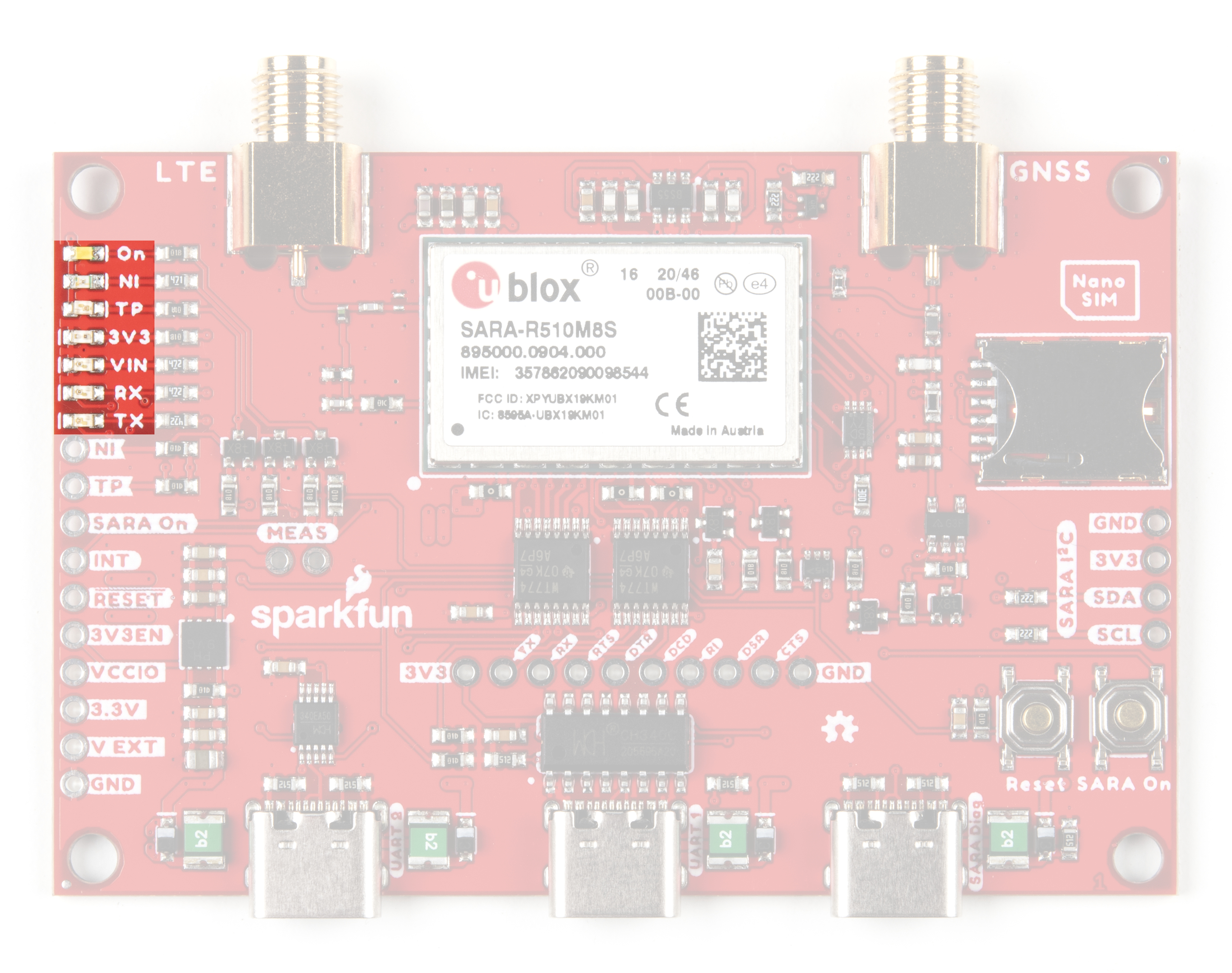
The voltage and power indicator LEDs are fairly self-explanatory. When power is applied to VIN or 3.3V, those respective indicator LEDs turn on (unless the solder jumpers tied to their respective circuits have been opened). The On LED indicates whether or not the SARA-R5 module is powered on. The RX and TX LEDs are tied to the RX/TX lines on UART1 to show when those are transmitting data.
The NI LED shows the cellular network status when GPIO1 is configured to act as a network status indicator output. The NI LED alternates from full Off (No service), full On (Data Transmission) as well as various pulse lengths to show different network statuses. Refer to section 17.1.3 of the AT Command Manual for the AT commands and description of this LED and the GPIO1/NI pin's behavior for different network states.
The TP LED can be configured as a visual indicator of the time pulse output signal to provide time information for the LTE system. When enabled, the LED will pulse once per second. Refer to section 17 of the AT Command Manual for the command set to configure this LED and TP/GPIO6 pin.
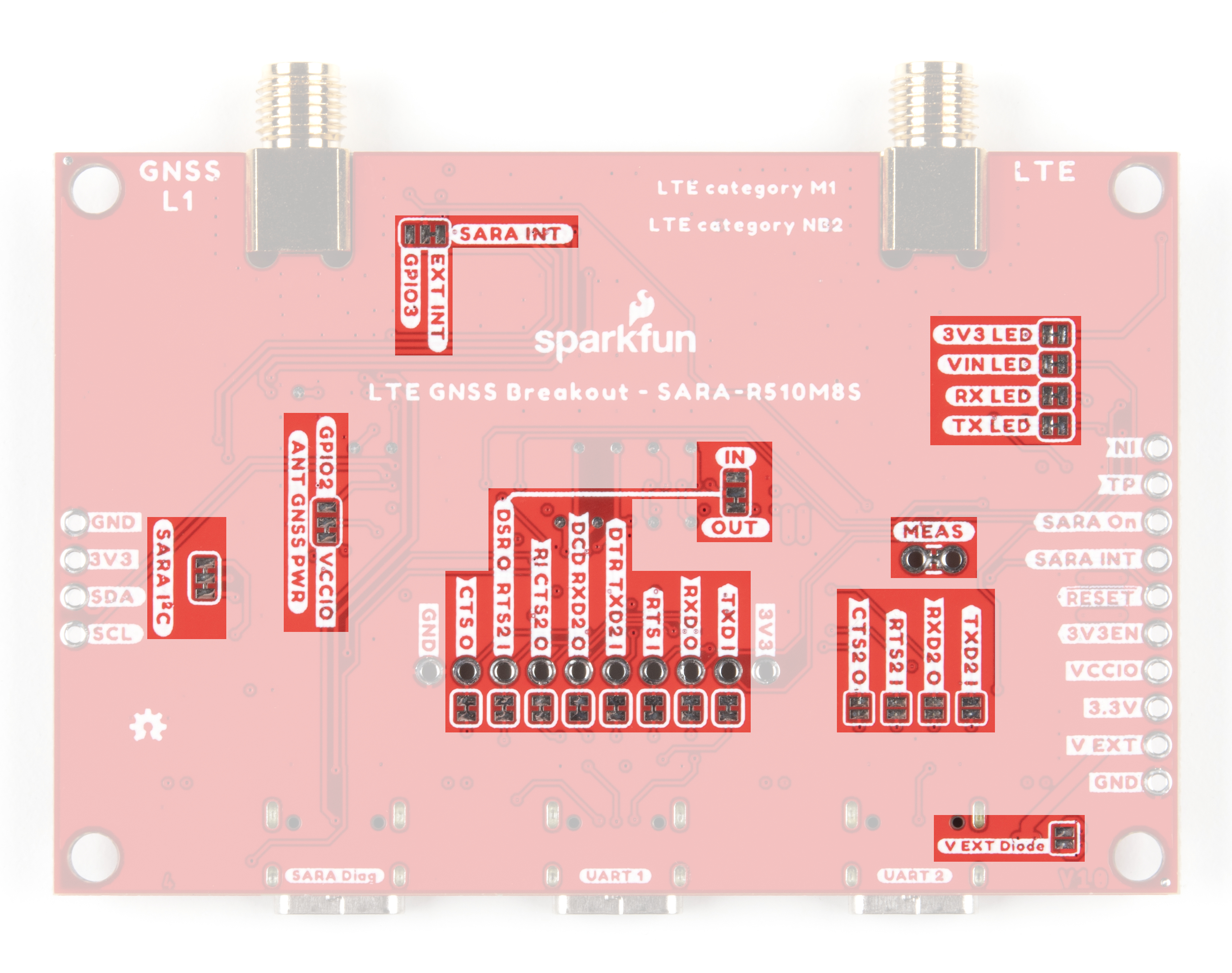
Solder Jumpers
The LTE/GNSS Breakout has a host of solder jumpers to adjust the behavior of the board and components on it. The tables below outline what each jumper does, their default states and some notes about their behavior.
| Jumper Label | Description | Default State | Notes |
|---|---|---|---|
| SARA I2C | Pulls SARA-R5 I2C lines to 3.3V via a pair of 2.2kΩ resistors. | CLOSED | |
| ANT GNSS PWR | A dual jumper to select power control for the GNSS antenna. | SEE NOTE | By default, GNSS antenna is tied to VCCIO to continuously power it. Switch the jumper from VCCIO to SARA GPIO2 to use that pin to control GNSS antenna power. |
| EXT INT / GPIO 3 | A dual jumper to select which SARA pin is tied to the SARA_INT PTH pin. | SEE NOTE | By default, this jumper routes the external interrupt pin to the PTH header. Adjust it to the pad labeled GPIO3 to tie this general purpose I/O pin to the PTH header instead. |
| IN/OUT | A dual jumper to select the direction of DSR (Data Set Ready) for dual UART communication. | SEE NOTE | By default, this jumper sets DSR as an output. Adjust the jumper to the "IN" side to set DSR as a flow control input. |
| MEAS | Current measuring jumper | CLOSED | Open this jumper to measure the current draw of the board with a multimeter. |
| V EXT Diode | V EXT diode bypass | OPEN | Close this jumper to bypass the external voltage input diode. |
| 3V3 LED | LED power control. | CLOSED | Open to disable the labeled LED. Disabling the LEDs helps reduce total current draw of the breakout. |
| VIN LED | CLOSED | ||
| RX LED | CLOSED | ||
| TX LED | CLOSED |
| Jumper Label | Description | Default State | Notes |
|---|---|---|---|
| TXD I | Ties UART1 TX line to the UART1 USB-C connector through the CH340C. | CLOSED | Open this jumper to isolate the TX pin from the USB-C connector for use with an Arduino or other device. |
| RXD O | Ties UART1 RX lne to the UART1 USB-C connector through the CH340C. | CLOSED | Open this jumper to isolate the RX pin from the USB-C connector for use with an Arduino or other device. |
| RTS I | Ties UART1 Request to Send to the UART1 USB-C connector through the CH340C. | CLOSED | Open this jumper to isolate the RTS pin from the CH340C and pull it LOW/0V via a 100kΩ resistor. The RTS pin must be pulled LOW/0V when using RX/TX only for serial communication as used in the Arduino library. |
| DTR TXD2 | CLOSED | Open this jumper to use DTR pin as UART2 data in (TX) for dual UART modes (when the TXD2_I jumper is CLOSED). If the TXD2_I jumper is OPEN, opening this jumper pulls the DTR pin LOW/0V to enable RX/TX only serial communication used in the Arduino library. | |
| DCD | CLOSED | Open the DCD jumper to use the DCD pin as UART2 data out (RX) for dual UART modes. | |
| RI CTS2 O | CLOSED | Open the RI CTS2 O jumper to use the RI pin as UART2 clear to send (CTS) for dual UART modes. | |
| DSR O RTS2 I | CLOSED | Open the DSR O RTS2 I jumper to use the DSR pin as UART2 request to send (RTS) for dual UART modes. | |
| CTS O | Ties UART1 Clear to Send to the UART1 USB-C connector through the CH340C. | CLOSED | Open this jumper to isolate the CTS pin from the USB-C connector for use with an Arduino or other device. |
| TXD2 I | Ties the labeled UART2 pin to the UART2 USB-C connector. | OPEN | Close these jumpers to connect the labeled UART2 pin to the UART2 USB-C connector. Using Dual UART modes requires other jumper manipulation. Read on to the Hardware Assembly section for more detailed instructions. |
| RXD2 O | OPEN | ||
| RTS2 I | OPEN | ||
| CTS2 O | OPEN |
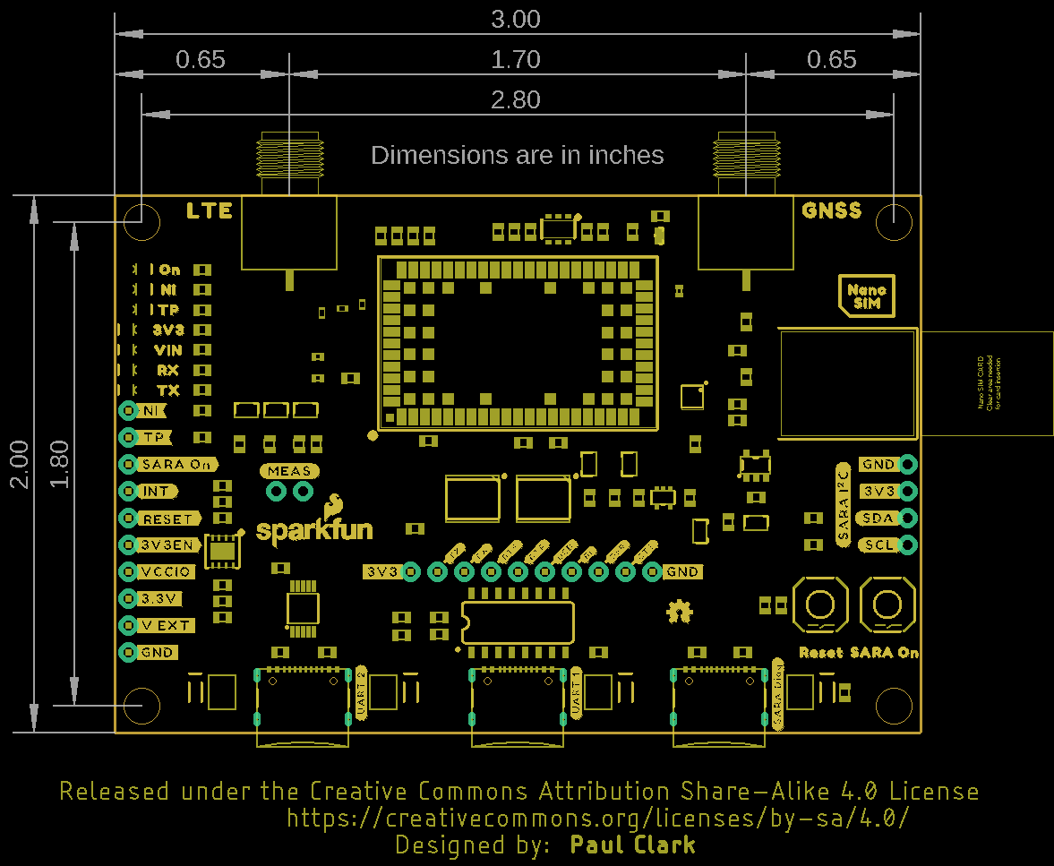
Board Dimensions
The SparkFun LTE GNSS Breakout - SARA-R5 measures 3.0in x 2.0in (76.2mm x 50.7mm) with four mounting holes that fit a 4-40 screw.
Hardware Assembly
In this section we'll go over the basics of connecting the LTE GNSS Breakout to your computer along with some tips on how to use it in some alternate configurations.
Basic Assembly
For quick basic assembly, connect the LTE and GNSS antennas to their respective SMA connectors and then plug in the board to your computer with a USB-C cable connected to the UART1 USB-C connector.
Your computer should automatically install any necessary USB drivers for the breakout when it is plugged in for the first time. In case your computer does not automatically install the USB drivers for the CH340 serial converter IC, read through our How to Install CH340 Drivers tutorial:
Dual UART Configuration
As covered in the Hardware Overview section, the LTE GNSS Breakout comes pre-configured for single UART behavior. In order to use one of the dual UART variants, make the following modifications to the board:
- Open the DTR, DCD, RI and DSR jumpers.
- Close the UART2 jumpers labeled TXD2, RXD2, RTS2 and CTS2
- Adjust the IN/OUT jumper from the "OUT" (default) position to the "IN" position.

Use the +USIO AT Command to select which variant you prefer. Refer to section 15.8 of the AT Command Set Manual for more information on the configuration selection command and section 1.9.1 of the System Integration Manual for detailed descriptions of the UART interface variants.
Arduino Assembly
Users who wish to use the LTE GNSS Breakout with an Arduino microcontroller need to solder to the board. If you are not familiar with through-hole soldering or want a refresher, take a look at this tutorial:
How to Solder: Through-Hole Soldering
September 19, 2013
Before soldering to the breakout, make the following adjustments to use the board with the u-blox SARA-R5 Arduino Library:
- Open the TXD_I, RXD_O, RTS_I and DTR/TXD2_I Solder Jumpers.
- Solder either headers or wire to the TXD I and RXD O PTH pins.
- Power the circuit using one of the following options:
- If powering the LTE GNSS Breakout from the Arduino, solder headers or wire to V_EXT PTH pin and one of the Ground PTHs.
- If powering the LTE GNSS Breakout and Arduino via the same power source (e.g. USB on the same computer), no power connections are necessary.
- If separate power supplies are used for both boards, make sure to create a common ground between the two circuits.
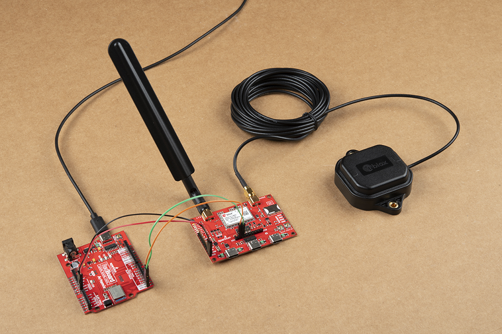
With the board modified, make the appropriate connections between the LTE GNSS Breakout and Arduino. The connections listed below assume the RedBoard/Arduino provides power to the LTE GNSS Breakout at 5V via USB:
- LTE GNSS TXD I → RedBoard TX1 (if using Serial1) or D9 (if using SoftwareSerial)
- LTE GNSS RXD O → RedBoard RX1 (if using Serial1) or D8 (if using SoftwareSerial)
- LTE GNSS V_EXT → RedBoard VIN
- LTE GNSS GND → RedBoard GND
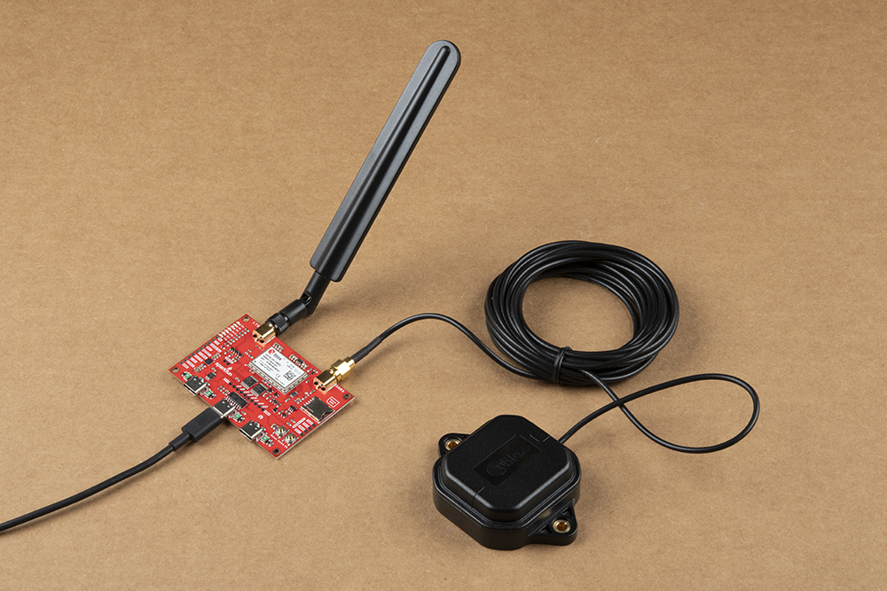
This tutorial uses a SparkFun RedBoard Artemis for the Arduino examples so the completed circuit looks like the photo below:
Software Setup
u-blox m-center
Interacting with the SARA-R5 over USB is a great way to get started with this breakout. For detailed instructions on installing and using the u-blox m-center software with your LTE GNSS Breakout - SARA-R5, head on over to the MicroMod Asset Tracker Update Tool Hookup Guide:
AT Command Set
For users who want to go right into directly manipulating the SARA-R5 using the AT Command Set, review the AT Command Manual from u-blox:
Read on to the next sections if you prefer to use the LTE GNSS Breakout - SARA-R5 with the SparkFun u-blox SARA-R5 Arduino Library.
SARA-R5 Arduino Library
The SparkFun u-blox SARA-R5 Arduino Library provides a quick way to interact with the interfaces on the LTE GNSS Breakout. Install the library through the Arduino Library Manager tool by searching for "SparkFun u-blox SARA-R5". Users who prefer to manually install the library can get it from the GitHub Repository or download the .ZIP by clicking the button below:
The library primarily works by associating a selection of AT Commands from the Command Set Manual with standard Arduino functions to run automatically in a sketch.
View the full list of AT Commands included in this library (along with all other available functions) in the header file. The list of included AT Commands starts on line 67.
Arduino Examples
The SparkFun u-blox SARA-R5 Arduino Library includes nine examples to cover how to configure and use different features of the SARA-R5 module. These examples are mostly intended to build on the previous one so we recommend going through them in sequential order in order to properly set up and use your LTE GNSS Breakout with an inserted SIM card.
If you have not used m-center or AT commands to configure the network information for operator selection and packet switched data (PSD) profiles prior to using this library, make sure to go through Example 3 - Network Info, Example 4 - Register Operator and Example 7 - Configure Packet Switched Data to get the SARA-R5 registered and configured properly on your mobile network.
Code Adjustments
We initially wrote this library for the MicroMod Asset Tracker Carrier Board so there are some unnecessary lines of code and minor adjustments needed to get everything running smoothly depending on your circuit and preferences. The information below outlines the common adjustments and we'll detail any adjustments for each example if needed.
LTE GNSS Breakout Adjustments
When using the LTE GNSS Breakout, feel free to comment out this line:
language:c
mySARA.invertPowerPin(true);
SoftwareSerial Adjustments
The SARA-R5 library automatically includes the SoftwareSerial.h file when a board that works with SoftwareSerial is selected. When using Software Serial in any of the examples, comment out this line:
language:c
#define saraSerial Serial1
and uncomment this line:
language:c
SoftwareSerial saraSerial(8, 9);
Adjust the pins for RX (8) and TX (9) depending on your selected board's limitations with the SoftwareSerial library.
Example 1 - GNSS GPRMC
The first example enables the GNSS receiver and reads the GPRMC message for position, speed and time data. Open the example by navigating to File>Examples>SparkFun u-blox SARA-R5 Arduino Library>SARA-R5_Example1_GNSS_GPRMC.
The breakout continuously powers the GNSS antenna by default so this line is unnecessary and can be commented out/deleted but if you have adjusted the ANT GNSS PWR jumper to use GPIO2 as a control pin, leave it as is.
language:c
mySARA.setGpioMode(mySARA.GPIO2, mySARA.GPIO_OUTPUT, 1);
Select your board in the Tools menu (in our case SparkFun RedBoard Artemis) and the correct Port it enumerated on and click "Upload". After uploading the code, open the Serial Monitor or terminal emulator of your choice with the baud rate set to 115200. The code waits for a keyboard input from the user before progresssing and running the setup and loop. After user input, the code prints out GPS data every second when there is a GPS lock.
Code to note. This function organizes the GPS data to print out neatly whenever the data returns as valid:
language:c
void printGPS(void)
{
  Serial.println();
  Serial.println("UTC: " + String(gps.utc));
  Serial.print("Time: ");
  if (clk.time.hour < 10) Serial.print('0'); // Print leading 0
  Serial.print(String(clk.time.hour) + ":");
  if (clk.time.minute < 10) Serial.print('0'); // Print leading 0
  Serial.print(String(clk.time.minute) + ":");
  if (clk.time.second < 10) Serial.print('0'); // Print leading 0
  Serial.print(String(clk.time.second) + ".");
  if (clk.time.ms < 10) Serial.print('0'); // Print leading 0
  Serial.println(String(clk.time.ms));
  Serial.println("Latitude: " + String(gps.lat, 7));
  Serial.println("Longitude: " + String(gps.lon, 7));
  Serial.println("Speed: " + String(spd.speed, 4) + " @ " + String(spd.cog, 4));
  Serial.println("Date (MM/DD/YY): " + String(clk.date.month) + "/" +
    String(clk.date.day) + "/" + String(clk.date.year));
  Serial.println("Magnetic variation: " + String(spd.magVar));
  Serial.println("Status: " + String(gps.status));
  Serial.println("Mode: " + String(gps.mode));
  Serial.println();
}
Example 2 - Identification
The second example prompts the LTE module to read the SARA-R5's identification information:
- Manufacturer ID
- Model
- Firmware Version
- Serial Number
- IMEI ID
- IMSI ID
- SIM CCID
- Subscriber Number (from the SIM)
- Capabilities
- SIM state
This example primarily functions as a check to make sure the SARA-R5 is working properly and the SIM card is detected then polls the SIM status in the main loop. Upload the code and open a terminal window with the baud set to 115200. The code initializes the SARA-R5 and after a user input, initializes the SARA-R5 and prints out the ID information and SIM state.
Example 3 - Network Info
This example verifies the SARA-R5 is receiving an LTE signal on a selected network and prints out the network information and IDs. The code creates the SARA-R5 object and assigns a network operator value. Depending on the network for your SIM card uses, adjust this line:
language:c
const mobile_network_operator_t MOBILE_NETWORK_OPERATOR = MNO_GLOBAL;
After uploading the code, open a terminal window with the baud set to 115200 and enter any key to start the example. After initializing everything needed, the code attempts to set the Network Profile to the Mobile Network Operator entered. If successful, the code prints out the RSSI (Received Signal Strength), Network Registration Status and Context IDs, Access Point Names and IP Addresses.
Example 4 - Register Operator
Example 4 checks to see if the SARA-R5 is connected to a network and lets you register on a different network if available and if the SIM supports this. This example can also be used to list all the LTE operators the SARA-R5 can detect. Note, you can only connect to networks supported by your SIM card. Refer to your SIM card manufacturer's documentation for supported networks.
Example 5 - Receive SMS
The fifth example demonstrates how to read and print any SMS text messages the SARA-R5 receives. The code checks whether the module is connected to an operator and will freeze if unsuccessful. If the code freezes here, wait and retry as it may be a connection issue with your network. Otherwise, return to Examples 3 and 4 to set set up the Network Operator.
The main loop accesses the message storage memory used for reading and deleting messages for data and prints the used and total number of memory locations in the message storage.
The code waits for any new messages to arrive and prints the Message Index (location), Status, Originator, Date and Time and then the message contents.
New messages are automatically marked as read once the code prints them. To force the code to print all the messages stored in the message memory, comment out this line:
language:c
if (unread == "REC UNREAD")
Example 6 - Send SMS
The sixth example sends SMS messages to another phone or LTE module from the LTE GNSS Breakout - SARA-R5. The code prompts the user for the destination number and message contents. In the Arduino Serial Monitor, just type both of these into the text box at the top and click Send or press ENTER.
Example 7 - Configure Packed Switched Data
Example 7 configures the "Context Identifier" for the mobile data connection. Make sure to go through this example to properly set up your SARA-R5 Context ID. Open a serial monitor with the baud set to 115200 and after the SARA initializes, press a key and then follow the prompts to select the appropriate Context ID. You may see a few Context IDs so make sure to select one that looks correct (i.e. not a blank IP):
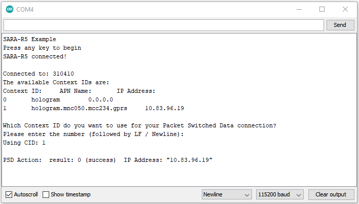
The code provides a warning that “deactivate profile failed”. We see this because the SARA needs to disconnect from a profile before it can connect to a new one, and in this case this failed because there was no profile active. Don't worry about this warning, it is just there for information. The example shows that our connection was successful by displaying the Internet Protocol (IP) address the SARA has been allocated by the service operator.
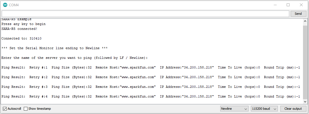
Example 8 - Ping
The eighth example tests the SARA's data connection by a standard server ping. Open a terminal window and follow the prompts then enter a server to ping. Any valid web address like www.google.com or www.sparkfun.com works. If the ping succeeds the code prints out the time to send and receive the ping in milliseconds.
If the ping fails, try uncommenting this line that enables debugging over serial:
language:c
assetTracker.enableDebugging(SERIAL_PORT);
Upload the code again, retry the ping and look for any messages that include +UUPINGER:. Refer to the list of Ping error codes in Appendix A. 10 of the AT Command Reference to decipher the error code.
For example, error 8 means the SARA "Cannot resolve host" which usually means a Domain Name Server (DNS) is not available. Error 17 indicates "Packet Switched Data connection not established". If you see this or similar errors, make sure you ran examples 3, 4 and 7 correctly and in the proper order as each builds on the previous example.
Example 9 - ThingSpeak
Heads Up! Unless using the Asset Tracker Carrier Board, the temperature data in the default code does not work as the LTE GNSS Breakout does not include the ICM-20948 9-DoF IMU found on the Asset Tracker.
We're including this example for completeness' sake but users will need to attach the 9DoF IMU Breakout to their microcontroller or modify the code to use other data for it to work properly.
The final example shows how to send data to ThingSpeak using HTTP POST or GET.
Make sure to complete these setup actions before using this example:
- Create a ThingSpeak User Account
- Create a new Channel by navigating to Channels → My channels → New Channel
- Check the Write API Key value and Copy/Paste it into
myWriteAPIKeyin the example.
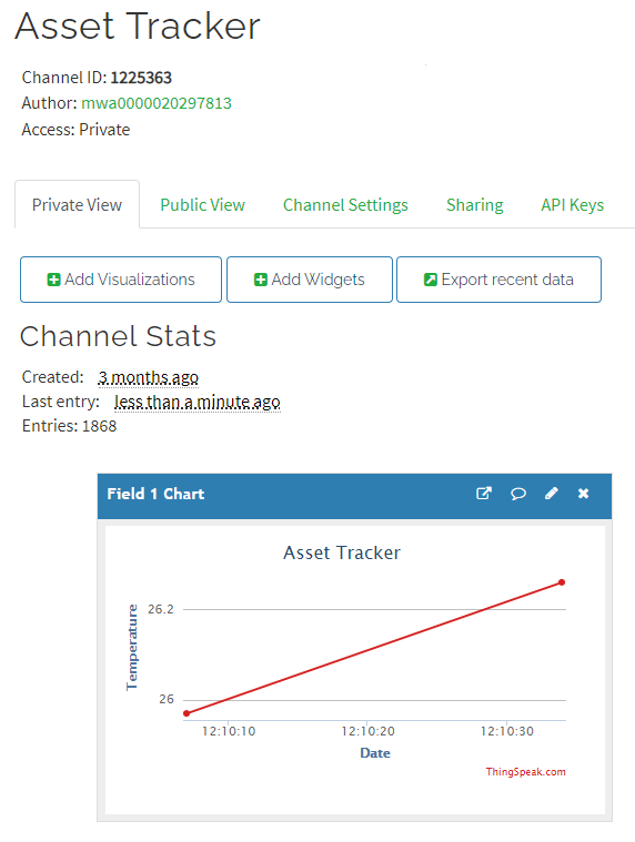
The main loop reads the temperature from the ICM-20948 and POSTs it to ThingSpeak. The data posts to your ThingSpeak channel as "Field 1".
Open a serial monitor with the baud set to 115200 to see the data sent to ThingSpeak printed out:
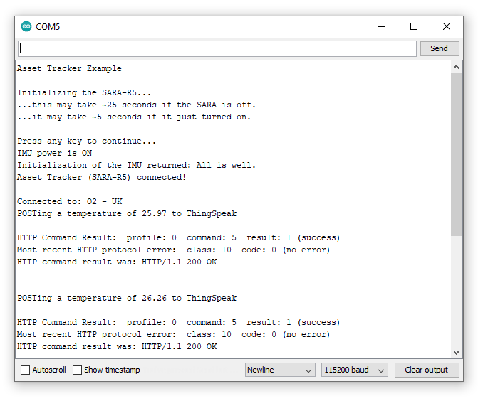
Check your ThingSpeak channel and you should see data posted to it similar to the screenshot below:
Troubleshooting
This section outlines a few troubleshooting tips and common snags when using the LTE GNSS Breakout - SARA-R5.
LTE Network Availability
The SARA-R5 supports LTE-M and NB-IoT data communication for multi-regional use. Please check the LTE signal availability for your area before purchasing a SARA-R5 product and selecting an LTE service provider / operator.
Data Connectivity
When working through the data connectivity examples, it is important that you run examples 13, 14 and 17 in order, before moving on to example 18 or 19. Each example builds on the last and together they configure the SARA’s data connection correctly.
TP (1PPS) Pin and LED
At the time of writing, we are shipping the SARA-R5 on the Asset Tracker with firmware version 02.06 on it. 02.06 contains a feature (which is just a polite name for a bug!) which means the 1 Pulse-Per-Second from the GNSS does work, but the pulse is only ~3 microseconds wide and cannot be adjusted. Handy huh? u-blox are aware of this - in fact we told them about it - and a fix is coming but they haven’t added it yet. We will keep an eye out for it and update this section once the fix is released.
Just to complicate matters, 3 microseconds is too short for the buffer FET and LED connected to the timing pulse to respond. So, we regret that you cannot currently use the TP PTH. We will share the fix with you as soon as we have it.
NB/IoT Compatibility
The SparkFun LTE GNSS Breakout - SARA-R5 uses the "00B" product version of the SARA-R5 module (specifically the SARA-R510M8S-00B-00). LTE NB-IoT Radio Access Technology, and the LTE FDD bands: 66, 71, 85 are not supported by this version.
Arduino Debug Messages
If you run into any trouble using one of the Arduino examples, uncomment this line:
language:c
assetTracker.enableDebugging(SERIAL_PORT);
This enables serial debugging to print out the full debug report from AT commands sent via functions in the library. Read through the data and search for matching error codes in Appendix A of the AT Command Reference manual to decipher the code.
General Troubleshooting Help
If you need technical assistance and more information on a product that is not working as you expected, we recommend heading on over to the SparkFun Technical Assistance page for some initial troubleshooting.
If you don't find what you need there, the SparkFun Forums: MicroMod are a great place to find and ask for help. If this is your first visit, you'll need to create a Forum Account to search product forums and post questions.
Resources and Going Further
That wraps up this Hookup Guide. For more information about the SparkFun LTE GNSS Breakout - SARA-R5 take a look at the resources below:
LTE GNSS Breakout - SARA-R5 Documentation:
- Schematic (PDF)
- Eagle Files (ZIP)
- Board Dimensions (PNG)
- SparkFun u-blox SARA-R5 Arduino Library
- Hardware GitHub Repository
u-blox SARA-R5 module Documentation:
- Datasheet (PDF)
- AT Command Set (PDF)
- System Integration Manual (PDF)
- Application Development Guide (PDF)
- Internet Applications Development Guide (PDF)
- GNSS Integration App Note (PDF)
- Firmware Update App Note (PDF)
For more information on using the SARA-R5 with u-blox m-center, check out the MicroMod Update Tool Hookup Guide (specifically the Software Setup section):