LTE GNSS Breakout - SARA-R5 Hookup Guide
 El Duderino,
  PaulZC
Arduino Examples
The SparkFun u-blox SARA-R5 Arduino Library includes nine examples to cover how to configure and use different features of the SARA-R5 module. These examples are mostly intended to build on the previous one so we recommend going through them in sequential order in order to properly set up and use your LTE GNSS Breakout with an inserted SIM card.
If you have not used m-center or AT commands to configure the network information for operator selection and packet switched data (PSD) profiles prior to using this library, make sure to go through Example 3 - Network Info, Example 4 - Register Operator and Example 7 - Configure Packet Switched Data to get the SARA-R5 registered and configured properly on your mobile network.
Code Adjustments
We initially wrote this library for the MicroMod Asset Tracker Carrier Board so there are some unnecessary lines of code and minor adjustments needed to get everything running smoothly depending on your circuit and preferences. The information below outlines the common adjustments and we'll detail any adjustments for each example if needed.
LTE GNSS Breakout Adjustments
When using the LTE GNSS Breakout, feel free to comment out this line:
language:c
mySARA.invertPowerPin(true);
SoftwareSerial Adjustments
The SARA-R5 library automatically includes the SoftwareSerial.h file when a board that works with SoftwareSerial is selected. When using Software Serial in any of the examples, comment out this line:
language:c
#define saraSerial Serial1
and uncomment this line:
language:c
SoftwareSerial saraSerial(8, 9);
Adjust the pins for RX (8) and TX (9) depending on your selected board's limitations with the SoftwareSerial library.
Example 1 - GNSS GPRMC
The first example enables the GNSS receiver and reads the GPRMC message for position, speed and time data. Open the example by navigating to File>Examples>SparkFun u-blox SARA-R5 Arduino Library>SARA-R5_Example1_GNSS_GPRMC.
The breakout continuously powers the GNSS antenna by default so this line is unnecessary and can be commented out/deleted but if you have adjusted the ANT GNSS PWR jumper to use GPIO2 as a control pin, leave it as is.
language:c
mySARA.setGpioMode(mySARA.GPIO2, mySARA.GPIO_OUTPUT, 1);
Select your board in the Tools menu (in our case SparkFun RedBoard Artemis) and the correct Port it enumerated on and click "Upload". After uploading the code, open the Serial Monitor or terminal emulator of your choice with the baud rate set to 115200. The code waits for a keyboard input from the user before progresssing and running the setup and loop. After user input, the code prints out GPS data every second when there is a GPS lock.
Code to note. This function organizes the GPS data to print out neatly whenever the data returns as valid:
language:c
void printGPS(void)
{
  Serial.println();
  Serial.println("UTC: " + String(gps.utc));
  Serial.print("Time: ");
  if (clk.time.hour < 10) Serial.print('0'); // Print leading 0
  Serial.print(String(clk.time.hour) + ":");
  if (clk.time.minute < 10) Serial.print('0'); // Print leading 0
  Serial.print(String(clk.time.minute) + ":");
  if (clk.time.second < 10) Serial.print('0'); // Print leading 0
  Serial.print(String(clk.time.second) + ".");
  if (clk.time.ms < 10) Serial.print('0'); // Print leading 0
  Serial.println(String(clk.time.ms));
  Serial.println("Latitude: " + String(gps.lat, 7));
  Serial.println("Longitude: " + String(gps.lon, 7));
  Serial.println("Speed: " + String(spd.speed, 4) + " @ " + String(spd.cog, 4));
  Serial.println("Date (MM/DD/YY): " + String(clk.date.month) + "/" +
    String(clk.date.day) + "/" + String(clk.date.year));
  Serial.println("Magnetic variation: " + String(spd.magVar));
  Serial.println("Status: " + String(gps.status));
  Serial.println("Mode: " + String(gps.mode));
  Serial.println();
}
Example 2 - Identification
The second example prompts the LTE module to read the SARA-R5's identification information:
- Manufacturer ID
- Model
- Firmware Version
- Serial Number
- IMEI ID
- IMSI ID
- SIM CCID
- Subscriber Number (from the SIM)
- Capabilities
- SIM state
This example primarily functions as a check to make sure the SARA-R5 is working properly and the SIM card is detected then polls the SIM status in the main loop. Upload the code and open a terminal window with the baud set to 115200. The code initializes the SARA-R5 and after a user input, initializes the SARA-R5 and prints out the ID information and SIM state.
Example 3 - Network Info
This example verifies the SARA-R5 is receiving an LTE signal on a selected network and prints out the network information and IDs. The code creates the SARA-R5 object and assigns a network operator value. Depending on the network for your SIM card uses, adjust this line:
language:c
const mobile_network_operator_t MOBILE_NETWORK_OPERATOR = MNO_GLOBAL;
After uploading the code, open a terminal window with the baud set to 115200 and enter any key to start the example. After initializing everything needed, the code attempts to set the Network Profile to the Mobile Network Operator entered. If successful, the code prints out the RSSI (Received Signal Strength), Network Registration Status and Context IDs, Access Point Names and IP Addresses.
Example 4 - Register Operator
Example 4 checks to see if the SARA-R5 is connected to a network and lets you register on a different network if available and if the SIM supports this. This example can also be used to list all the LTE operators the SARA-R5 can detect. Note, you can only connect to networks supported by your SIM card. Refer to your SIM card manufacturer's documentation for supported networks.
Example 5 - Receive SMS
The fifth example demonstrates how to read and print any SMS text messages the SARA-R5 receives. The code checks whether the module is connected to an operator and will freeze if unsuccessful. If the code freezes here, wait and retry as it may be a connection issue with your network. Otherwise, return to Examples 3 and 4 to set set up the Network Operator.
The main loop accesses the message storage memory used for reading and deleting messages for data and prints the used and total number of memory locations in the message storage.
The code waits for any new messages to arrive and prints the Message Index (location), Status, Originator, Date and Time and then the message contents.
New messages are automatically marked as read once the code prints them. To force the code to print all the messages stored in the message memory, comment out this line:
language:c
if (unread == "REC UNREAD")
Example 6 - Send SMS
The sixth example sends SMS messages to another phone or LTE module from the LTE GNSS Breakout - SARA-R5. The code prompts the user for the destination number and message contents. In the Arduino Serial Monitor, just type both of these into the text box at the top and click Send or press ENTER.
Example 7 - Configure Packed Switched Data
Example 7 configures the "Context Identifier" for the mobile data connection. Make sure to go through this example to properly set up your SARA-R5 Context ID. Open a serial monitor with the baud set to 115200 and after the SARA initializes, press a key and then follow the prompts to select the appropriate Context ID. You may see a few Context IDs so make sure to select one that looks correct (i.e. not a blank IP):
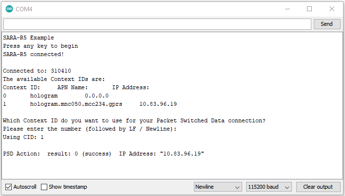
The code provides a warning that “deactivate profile failed”. We see this because the SARA needs to disconnect from a profile before it can connect to a new one, and in this case this failed because there was no profile active. Don't worry about this warning, it is just there for information. The example shows that our connection was successful by displaying the Internet Protocol (IP) address the SARA has been allocated by the service operator.
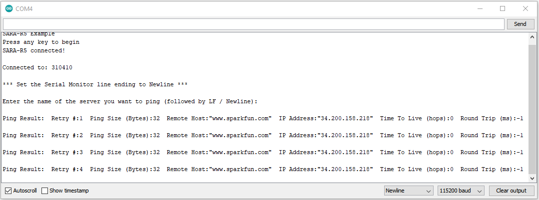
Example 8 - Ping
The eighth example tests the SARA's data connection by a standard server ping. Open a terminal window and follow the prompts then enter a server to ping. Any valid web address like www.google.com or www.sparkfun.com works. If the ping succeeds the code prints out the time to send and receive the ping in milliseconds.
If the ping fails, try uncommenting this line that enables debugging over serial:
language:c
assetTracker.enableDebugging(SERIAL_PORT);
Upload the code again, retry the ping and look for any messages that include +UUPINGER:. Refer to the list of Ping error codes in Appendix A. 10 of the AT Command Reference to decipher the error code.
For example, error 8 means the SARA "Cannot resolve host" which usually means a Domain Name Server (DNS) is not available. Error 17 indicates "Packet Switched Data connection not established". If you see this or similar errors, make sure you ran examples 3, 4 and 7 correctly and in the proper order as each builds on the previous example.
Example 9 - ThingSpeak
Heads Up! Unless using the Asset Tracker Carrier Board, the temperature data in the default code does not work as the LTE GNSS Breakout does not include the ICM-20948 9-DoF IMU found on the Asset Tracker.
We're including this example for completeness' sake but users will need to attach the 9DoF IMU Breakout to their microcontroller or modify the code to use other data for it to work properly.
The final example shows how to send data to ThingSpeak using HTTP POST or GET.
Make sure to complete these setup actions before using this example:
- Create a ThingSpeak User Account
- Create a new Channel by navigating to Channels → My channels → New Channel
- Check the Write API Key value and Copy/Paste it into
myWriteAPIKeyin the example.
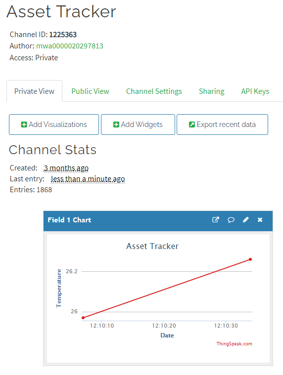
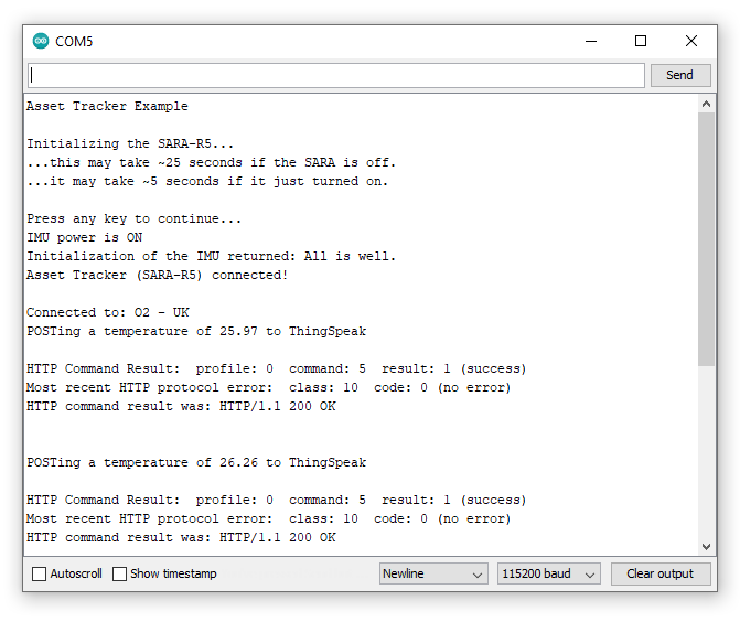
The main loop reads the temperature from the ICM-20948 and POSTs it to ThingSpeak. The data posts to your ThingSpeak channel as "Field 1".
Open a serial monitor with the baud set to 115200 to see the data sent to ThingSpeak printed out:
Check your ThingSpeak channel and you should see data posted to it similar to the screenshot below: