Ludus Protoshield Hookup Guide
This Tutorial is Retired!
This tutorial covers concepts or technologies that are no longer current. It's still here for you to read and enjoy, but may not be as useful as our newest tutorials.
View the updated tutorial: Wireless Motor Driver Shield Hookup Guide
 Nick Poole
Simple Motor Control
In this section, we'll review how to connect a pair of motors to the Ludus ProtoShield and get them spinning. Before we do that, however, let's talk a little bit about how we talk to the H-Bridge Driver. If we look at the datasheet for the TB6612FNG we find a table like this:
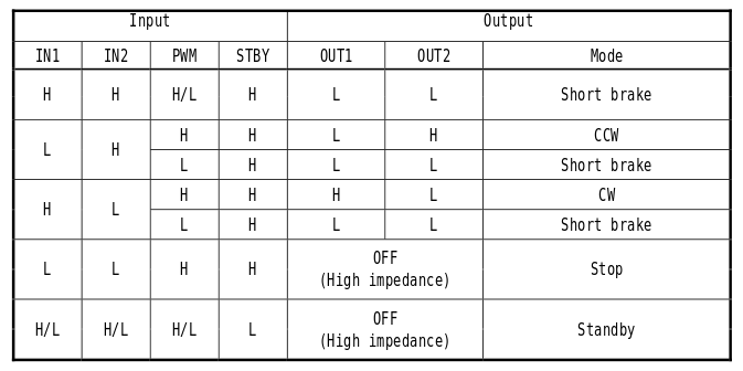
This table shows the relationship between the input and output pins on the H-Bridge. Each of the two channels requires 3 pins to operate: IN1, IN2 and PWM. By driving the IN pins high or low, you can control the direction of the motor on that channel as well as disengage it completely or even short it end-to-end (like pressing the brakes). The signal that you feed to the PWM pin determines the speed of the motor on that channel. By referencing the table above, we discover that in order to make the motor turn clockwise at 50% speed, we'll need set IN1 to High, IN2 to LOW and send a 50% PWM signal (that's analogWrite(pin, 128) in Arduino)
We can look at the silkscreen on the shield itself to find out which Arduino pins are connected to which inputs on the H-Bridge. Once we know that, we can start to write some basic example code to control the driver.
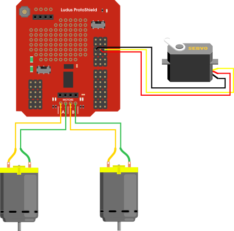
Before anything is going to move, we'll need to connect a pair of motors. If you're just starting out with robotics, we suggest the DAGU Hobby Gearmotors which are the same ones that come with our Ardumoto Shield Kit. Solder a pair of jumper wires to each of the gearmotors, and plug them into the A+, A-, B+ and B- headers. The example code also allows you to control a servo, so if you'd like to add a servo, plug it into pin 11.
Now, attach the shield to an Arduino or SparkFun RedBoard and connect a power supply, such as a 9V battery. Once that's done, we can get the example code loaded onto the Arduino.
Grab the example code from the GitHub repository here, and open it in Arduino. Connect your RedBoard or Arduino over USB, and make sure you have the correct board type and COM port selected. Now press "upload" to send the example code to the board!
If everything went well, you should now be able to open a serial terminal (such as the one built into the Arduino IDE), and type a bunch of "w"s to make the motors turn. This example was really written to be used with terminal programs, which allow you to type directly to the port without having to press return. That way, you can drive the robot by holding down the appropriate keys on your keyboard. My favorite terminal program for this is RealTerm. You can get RealTerm here.
Now that we've seen this thing in action, let's dig through the example code. Understanding how the example code works is the first step towards writing your own!