Lumenati Hookup Guide
 Pete-O
Multiple Board Assembly
This section will cover the steps necessary to connect multiple Lumenati boards together.
Plan the Layout
For our demonstration, we'll use four Lumenati 90L boards combined with a Lumenati 8-pack for a chain of 20 LEDs. Then we'll drive them with a Raspberry Pi 3 in our first example and a SAMD21 Breakout in the second.
To begin, gather the boards you want to use.
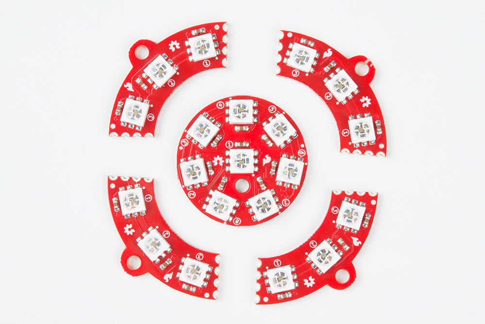
You may want to sand or file down some of the edges left from the panelization of the PCBs to aid in fitment at this point, but we'll leave that up to your judgement.
Soldering!
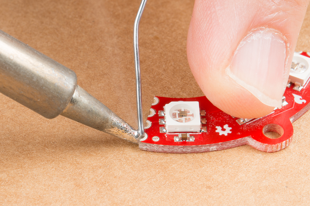
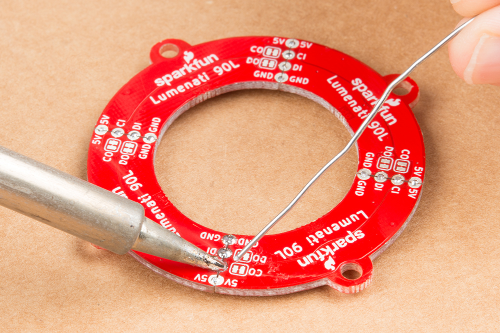
The four 90L boards will form a contiguous ring of LEDs. It would be difficult to get the clock and data signals off of the last 90L board (not impossible, but difficult), so we're going to put the 8-pack at the beginning of the chain. First, we'll solder up the four 90L's. To do this, you'll need a flat surface, preferably one that doesn't burn too much. A piece of cardboard works really great for this! Tin one of the corner connections (either power or ground) on one of the boards with some solder, like so:
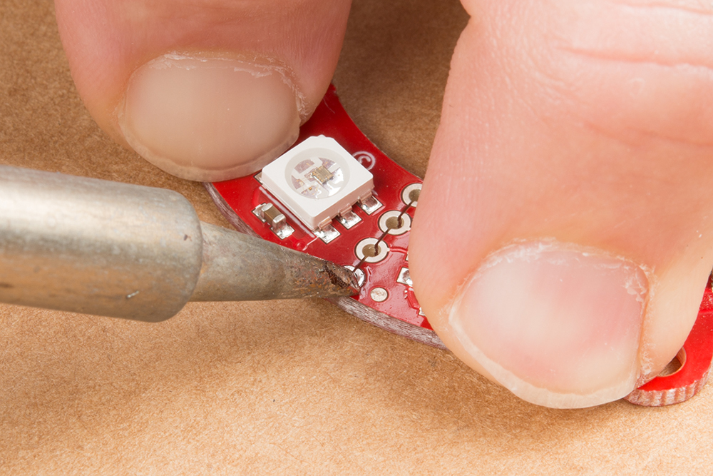
Then, butt the board you've just tinned up against the next board you want in the sequence, and reheat that solder you just placed so that it bridges between the two boards and forms enough of a mechanical connection to hold them together. Take care to make sure that both boards are as flat as you can get them to maximize both electrical and mechanical connections.
After you secure the first connection, solder the other three on both the top and bottom. This will make the boards as strong as possible. However, be aware that these can still break apart if put under too much stress. Mounting the boards to a solid backing is recommended, but they should still hold together fairly well if you're making something like a Christmas ornament or the like. For our demonstration, we're going to leave all the boards unmounted.
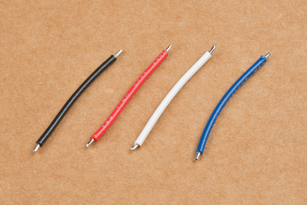
Next, solder the leads between the 8-pack and the four 90L boards. Cut four lengths of wire about 1 inch in length. We suggest color coding your wires for power (red), ground (black), clock and data (your call on those). Strip both ends of each wire about 1/16 inch to 1/8 inch, and tin them.
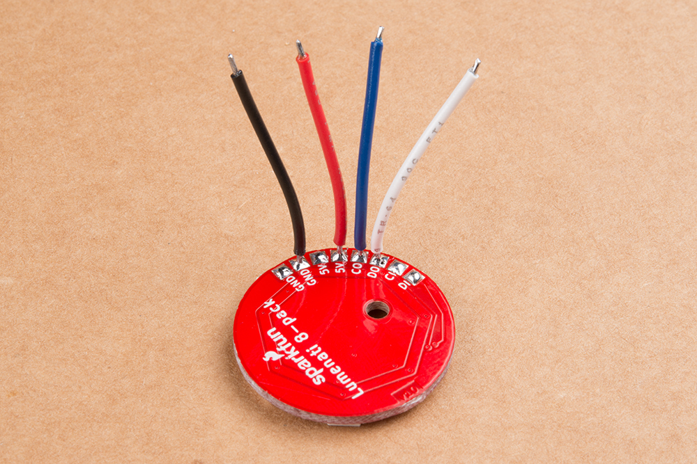
Tin all the solder pads of the 8-pack and solder your four leads to 5V (either of the two 5V pads), ground (either of the ground pads), CO and DO (Clock Out and Data Out). You can lay them out to the side if you wish, but we're going to sit them straight up so as to make positioning of the PCB easier.
Place the 8-pack board in the middle of the circle of 90L boards you've already made. Figure out how you'd like the board oriented, and pick one of the four interfaces between the four 90L boards to which you'll solder your four leads.
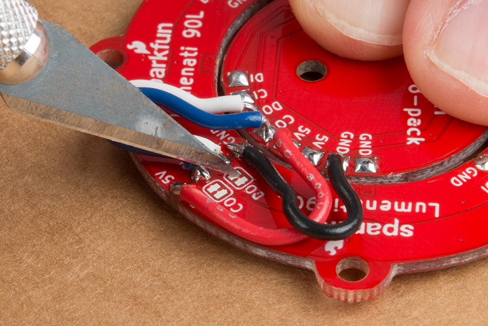
Once you've done that, solder down your leads - 5V to 5V, GND to GND, CO on the 8-pack to CI on the circle, and DO on the 8-pack to DI on the circle.
An alternate method of wiring to the 90L circle would be to solder up three of the four board interfaces leaving the fourth as open holes into which you can insert your 5V, GND, CO and DO lines. You will have to determine what your positioning is going to be before doing so.
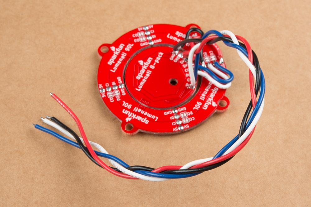
Now, you need to get power and signal to the thing you've constructed. To do so, just solder four more leads to the remaining 5V and GND pads on the 8-pack board, as well as CI and DI on the 8-pack. Braid the wires for some extra geek-cred. Now, it's ready to hook up to your control system!